
If you've spent any time configuring user authentication on... Full Story
By Manny Fernandez
November 9, 2026
Spanning Tree Protocol Explained: STP vs RSTP vs MSTP (with FortiSwitch Config)
Spanning Tree Protocol Explained: STP vs RSTP vs MSTP (with FortiSwitch Config)
No fluff. Just the config that works.
Executive Summary
The spanning tree protocol is the reason a Layer 2 network with redundant links does not melt into a broadcast storm. It has also evolved three times: classic STP (IEEE 802.1D), Rapid Spanning Tree (RSTP, IEEE 802.1w) and Multiple Spanning Tree (MSTP, IEEE 802.1s, now folded into 802.1Q). Most outages I get called into are not caused by spanning tree failing, they are caused by people not knowing which version is running, where the root bridge lives, or why half their uplinks sit idle.
- Objective: understand how STP, RSTP and MSTP elect a root and block loops, why RSTP converges in under a second where 802.1D takes up to 50 seconds, and how MSTP maps VLANs to instances so both core uplinks carry traffic. Then build it on FortiLink-managed FortiSwitch units, with a Cisco IOS equivalent.
- Target audience: network and security engineers who run campus or branch switching, FortiGate admins managing FortiSwitch through FortiLink, and anyone studying for a switching certification who wants the practitioner version.
Prerequisites and Architecture
Assumed knowledge
- VLANs and 802.1Q trunking.
- MAC address learning and why a Layer 2 loop has no TTL to kill it.
- Basic FortiGate CLI and FortiLink switch management (or Cisco IOS for the alternate config).
Lab requirements
- One FortiGate acting as FortiLink switch controller (FortiOS 7.4 or 7.6).
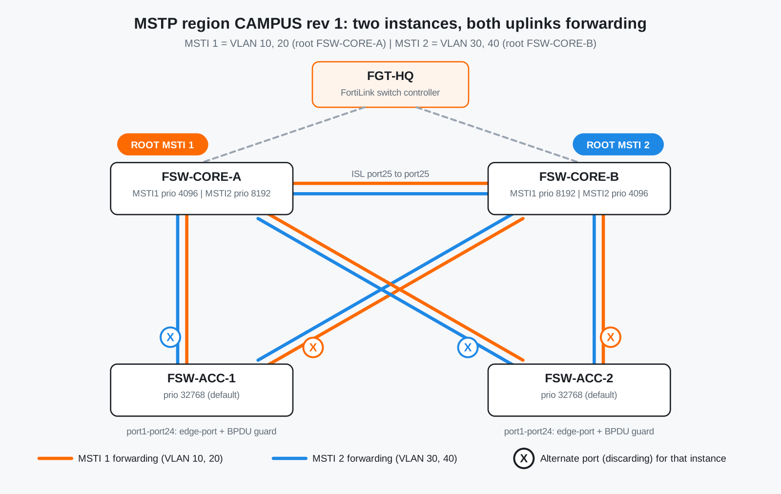
- Two core FortiSwitch units and two access FortiSwitch units, cabled in a full mesh between the core and access layers, plus an inter-switch link between the cores.
- Four user VLANs:
vlan10,vlan20,vlan30,vlan40with SVIs in 10.0.10.0/24 through 10.0.40.0/24 on the FortiGate.
| Component | Role | MSTI 1 priority | MSTI 2 priority |
|---|---|---|---|
| FGT-HQ | FortiLink controller, VLAN SVIs 10.0.10.1 to 10.0.40.1 | n/a | n/a |
| FSW-CORE-A | Core switch, root for MSTI 1 (VLAN 10, 20) | 4096 | 8192 |
| FSW-CORE-B | Core switch, root for MSTI 2 (VLAN 30, 40) | 8192 | 4096 |
| FSW-ACC-1 | Access switch, user ports port1 to port24 | 32768 (default) | 32768 (default) |
| FSW-ACC-2 | Access switch, user ports port1 to port24 | 32768 (default) | 32768 (default) |
Figure 1
How the Spanning Tree Protocol Works (802.1D)
Every version of spanning tree runs the same core algorithm. Switches exchange Bridge Protocol Data Units (BPDUs), agree on one root bridge, and then every other switch keeps exactly one best path toward that root. Every other redundant path is blocked.
Step 1: elect the root bridge
The root is the switch with the lowest Bridge ID. The Bridge ID is 8 bytes: a 2-byte priority field followed by the 6-byte base MAC address. On modern switches the priority field is split into a 4-bit priority (so it moves in steps of 4096) and a 12-bit extended system ID that carries the VLAN or instance number. Leave every switch at the default 32768 and the oldest switch with the lowest MAC wins the election, which is how a closet switch from 2011 ends up as root of your data center.
Step 2: pick root ports, designated ports, and block the rest
- Root port: on every non-root switch, the one port with the lowest total path cost to the root. Ties break on the sender Bridge ID, then the sender port priority and port number.
- Designated port: on every segment, the one port that offers the best path to the root. All ports on the root bridge are designated.
- Blocked port: everything else. It still listens to BPDUs but does not forward frames.
| Link speed | 802.1D-1998 cost (short) | 802.1t / RSTP cost (long) |
|---|---|---|
| 10 Mbps | 100 | 2,000,000 |
| 100 Mbps | 19 | 200,000 |
| 1 Gbps | 4 | 20,000 |
| 10 Gbps | 2 | 2,000 |
| 100 Gbps | not defined | 200 |
Gotcha: Mixing switches that use short costs with switches that use long costs gives you a root path that looks nothing like your diagram. FortiSwitch uses long costs (20,000 for 1 Gbps). Check your other vendors and make it consistent.
Step 3: wait for the timers
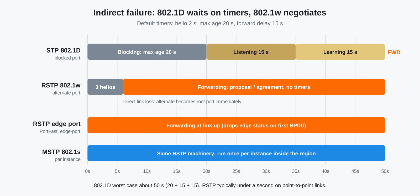
Classic 802.1D does not negotiate. A port that needs to start forwarding walks through Blocking, Listening, Learning and finally Forwarding, driven by three timers: hello (2 seconds), max age (20 seconds) and forward delay (15 seconds). If an indirect link fails, a blocked port waits for max age to expire before it even starts, so worst-case recovery is 20 + 15 + 15 = 50 seconds. A directly connected failure still costs 30 seconds. Topology changes are reported with Topology Change Notification BPDUs relayed to the root, which then tells everyone to age MAC tables quickly.
Figure 2
Rapid Spanning Tree (RSTP, 802.1w)
RSTP keeps the 802.1D election rules and BPDU format and changes how ports move to forwarding. It was folded into 802.1D-2004, which removed the original STP from the standard entirely. Everything modern runs RSTP or something built on it.
Port roles and states
| 802.1D state | RSTP state | RSTP roles that can use it |
|---|---|---|
| Disabled, Blocking, Listening | Discarding | Alternate, Backup, Disabled, (Root and Designated while syncing) |
| Learning | Learning | Root, Designated |
| Forwarding | Forwarding | Root, Designated |
- Alternate port: a pre-computed backup path to the root. If the root port dies, the alternate takes over immediately with no timers.
- Backup port: a second port on the same shared segment as a designated port. Rare outside hubs.
- Edge port: a port facing an end host. It forwards at link up, and drops back to a normal STP port the moment it hears a BPDU. Cisco calls this PortFast; FortiSwitch calls it
edge-port.
What makes it rapid
- Proposal and agreement: on point-to-point links, a designated port sends a proposal, the downstream switch syncs (blocks its own non-edge designated ports), then replies with an agreement. The link forwards in milliseconds and the sync ripples down the tree.
- BPDUs as keepalives: every bridge sends BPDUs every hello time, not just the root. Three missed hellos (6 seconds) means the neighbor is gone, instead of waiting 20 seconds of max age.
- Faster topology change: the switch that detects the change floods TC BPDUs itself and flushes MAC entries on its non-edge ports, instead of relaying a notification to the root first.
- Link type matters: rapid transition only works on point-to-point (full duplex) links. Half-duplex links fall back to timer behavior.
RSTP is backward compatible on a per-port basis: if it hears an 802.1D BPDU, that port drops to legacy behavior. One forgotten legacy switch can quietly put a chunk of your network back on 30 to 50 second convergence.
Multiple Spanning Tree (MSTP, 802.1s)
RSTP fixes speed, but it still builds one tree for every VLAN. In Figure 1 that means one core is root and every access uplink to the other core blocks for all VLANs: you paid for two uplinks and use one. Cisco solved this with Per-VLAN Spanning Tree (PVST+ and Rapid PVST+), which runs one tree per VLAN. That works, but 500 VLANs means 500 tree instances and 500 sets of BPDUs. MSTP is the IEEE middle ground: you map many VLANs onto a small number of instances and each instance gets its own tree.
Region, instances, and the IST
- MST region: a group of switches that agree on three things: the region name, the revision number, and the identical VLAN to instance mapping. The mapping is carried as a digest in the BPDU, so a single VLAN mapped differently splits the region.
- IST (instance 0, MSTI 0): the Internal Spanning Tree. It is the only instance that sends BPDUs; information for every other instance rides inside it as M-records. Timers are therefore set once per region, not per instance.
- MSTI 1 to n: the instances you create. Each has its own root and its own port roles, so you can make Core A root for MSTI 1 and Core B root for MSTI 2.
- CST and CIST: outside the region, the whole region looks like one big virtual bridge in a Common Spanning Tree. The Common and Internal Spanning Tree (CIST) is the IST inside every region joined with the CST between them.
- Max hops: inside a region, BPDU lifetime is controlled by a hop count (default 20) instead of max age.
Gotcha: FortiSwitch supports 15 MST instances per region on most models (instance IDs up to 32 on 5xx and higher). Under FortiLink, instance 15 is used for VLAN 4094 and the FortiLink trunks, so build your user instances from 1 upward and leave 15 alone.
Choosing a version
| Protocol | Standard | Trees | Convergence | Use it when |
|---|---|---|---|---|
| STP | 802.1D-1998 | 1 for all VLANs | 30 to 50 s | Never on purpose |
| RSTP | 802.1w, 802.1D-2004 | 1 for all VLANs | Under 1 s typical | Small flat networks, single core |
| Rapid PVST+ | Cisco proprietary | 1 per VLAN | Under 1 s typical | All-Cisco campus with few VLANs |
| MSTP | 802.1s, 802.1Q | 1 per instance | Under 1 s typical | Multi-vendor, many VLANs, dual core |
Spanning tree is the safety net, not the only way to use both uplinks. If the access switch can bundle its uplinks into one logical link, nothing needs to block at all: see LACP (802.3ad) link aggregation for the bundle itself and FortiSwitch MCLAG configuration for spanning the bundle across two core switches. Keep spanning tree running underneath either way.
Step-by-Step Implementation on FortiSwitch (FortiLink)
Managed FortiSwitch units run MSTP by default, and MSTP talks to STP and RSTP neighbors. You configure it centrally on the FortiGate. Replace the serial numbers below with your own from execute switch-controller get-conn-status.
Gotcha: STP does not run between the FortiGate and the FortiSwitch on the FortiLink itself. The design below handles loops between switches; the FortiLink trunk is not part of the tree.
Step 1: Define the MST region
Goal
Give every managed switch the same region name and revision so they form one region.
Action
config switch-controller stp-settings
    set name "CAMPUS"
    set revision 1
    set hello-time 2
    set forward-time 15
    set max-age 20
    set max-hops 20
end
GUI Verification
WiFi and Switch Controller, FortiSwitch Ports shows no STP alarms. The values above are the defaults for the timers, so only name and revision actually change anything; they are listed so you can see what is tunable.
Step 2: Map VLANs to instances
Goal
Split the four VLANs across two instances. The mapping must be identical on every switch, which FortiLink guarantees because it pushes the same table to all of them.
Action
config switch-controller stp-instance
    edit "1"
        set vlan-range "vlan10" "vlan20"
    next
    edit "2"
        set vlan-range "vlan30" "vlan40"
    next
end
GUI Verification
Any VLAN you do not map stays in instance 0 (the IST). That is fine for management VLANs, just know where they live.
Step 3: Place the root bridge for each instance
Goal
Make FSW-CORE-A root for MSTI 1 and FSW-CORE-B root for MSTI 2, each acting as the secondary root for the other. Also pin instance 0 to Core A so the IST root is predictable.
Action
config switch-controller managed-switch
    edit "S448ENTF00000001"
        config stp-instance
            edit "0"
                set priority 4096
            next
            edit "1"
                set priority 4096
            next
            edit "2"
                set priority 8192
            next
        end
    next
    edit "S448ENTF00000002"
        config stp-instance
            edit "0"
                set priority 8192
            next
            edit "1"
                set priority 8192
            next
            edit "2"
                set priority 4096
            next
        end
    next
end
GUI Verification
Priority must be a multiple of 4096 (0 to 61440). Leave the access switches at 32768 so they can never win.
Step 4: Edge ports and BPDU guard on user ports
Goal
Let laptops and phones forward instantly, and shut any user port down if a switch shows up on it.
Action
config switch-controller managed-switch
    edit "S248EPTF00000003"
        config ports
            edit "port1"
                set stp-state enabled
                set edge-port enabled
                set stp-bpdu-guard enabled
                set stp-bpdu-guard-time 10
            next
        end
    next
end
Repeat for port1 to port24 on both access switches (a short script or FortiManager template saves your wrists). stp-bpdu-guard-time is how long, in minutes, the port stays down after a BPDU arrives: default 5, maximum 120, and 0 means it stays down until you reset it.
GUI Verification
WiFi and Switch Controller, FortiSwitch Ports: the user ports show Edge Port and BPDU Guard enabled.
Step 5: Root guard on core downlinks
Goal
Stop anything below the core from ever becoming root, even if someone plugs in a switch with priority 0 on a trunk where BPDU guard is not an option.
Action
config switch-controller managed-switch
    edit "S448ENTF00000001"
        config ports
            edit "port1"
                set stp-root-guard enabled
            next
            edit "port2"
                set stp-root-guard enabled
            next
        end
    next
end
Apply it on the downlinks of both cores toward the access layer (the designated ports). Never enable root guard on a root port or on the inter-core link.
GUI Verification
A port that receives a superior BPDU with root guard on is held discarding for that instance instead of moving the root.
Step 6 (optional): Cisco IOS equivalent
Goal
If the core is Cisco, the same region must be configured identically for the FortiSwitch access layer to join it as one region.
Action
spanning-tree mode mst
spanning-tree mst configuration
 name CAMPUS
 revision 1
 instance 1 vlan 10,20
 instance 2 vlan 30,40
 exit
spanning-tree mst 0-1 priority 4096
spanning-tree mst 2 priority 8192
!
interface range GigabitEthernet1/0/1 - 24
 spanning-tree portfast
 spanning-tree bpduguard enable
GUI Verification
show spanning-tree mst configuration must show the same name, revision and instance table as the FortiSwitch side. The second core gets the priorities reversed.
Verification and Validation
From the FortiGate, check each instance on each core:
diagnose switch-controller switch-info stp S448ENTF00000001 1Expected success output on FSW-CORE-A for MSTI 1 (trimmed):
MST Instance Information, primary-Channel:
Instance ID :   1
Switch Priority : 4096
Root MAC Address :    704ca5000001
Root Priority:    4096
Root Pathcost:    0
This bridge is the root

Port        Speed  Cost   Priority  Role        State       Edge
port1       10G    2000   128       DESIGNATED  FORWARDING  NO
port2       10G    2000   128       DESIGNATED  FORWARDING  NO
port25      10G    2000   128       DESIGNATED  FORWARDING  NO
Run the same command against FSW-ACC-1 for instance 1 and then instance 2. The uplink toward Core A should be ROOT / FORWARDING in instance 1 and ALTERNATE / DISCARDING in instance 2, and the opposite for the uplink toward Core B. That is the whole point: both uplinks carry traffic, each for its own VLANs.
diagnose switch-controller switch-info bpdu-guard-status S248EPTF00000003Every user port should show enabled with a count of 0. On a Cisco core, the equivalents are:
show spanning-tree mst configuration
show spanning-tree mst 1
show spanning-tree mst 2 detail
show spanning-tree inconsistentports
Final test: shut the uplink from FSW-ACC-1 to Core A while a continuous ping runs from a host in VLAN 10 to 10.0.10.1. With RSTP machinery and point-to-point links you should lose zero to one ping, not thirty.
Troubleshooting and Gotchas
1. Region mismatch: switches that should be one region are two
Symptom: the access switch shows its uplinks as boundary ports, instance 1 and instance 2 have the same root everywhere, and one uplink blocks for every VLAN. Cause: a different region name, a different revision, or one VLAN mapped differently (very common when a Cisco core and a FortiSwitch access layer are configured by different people). Diagnose: compare show spanning-tree mst configuration on the Cisco side with show switch-controller stp-settings and show switch-controller stp-instance on the FortiGate. Fix: make name, revision and the full VLAN table identical, including VLANs that do not exist on one side yet.
2. A user port went down and nobody touched it
Symptom: a desk port is dead, often right after someone plugged in a small unmanaged or managed switch to get more ports. Cause: BPDU guard did its job. Diagnose: diagnose switch-controller switch-info bpdu-guard-status <serial> shows the port, the count and the last event. Fix: remove the switch, then wait for stp-bpdu-guard-time to expire or, on a standalone FortiSwitch, run execute bpdu-guard reset <port>. If that port legitimately needs a downstream switch, make it a proper trunk with root guard instead.
3. My priorities do not stick on managed FortiSwitch
Symptom: you set priorities but the root bridge is not where you put it. Cause: FortiLink can assign STP priority automatically, and auto-stp-priority on the switch takes precedence; Fortinet also warns that changing that setting briefly drops FortiLink. Diagnose: diagnose switch-controller switch-info stp <serial> 0 and check Switch Priority against your config. Fix: set the per-switch instance priorities as in Step 3 and, where Fortinet guidance calls for it, disable auto-stp-priority during a maintenance window. When the network contains Rapid PVST+ switches, enable set rpvst-port enabled on the boundary ports and keep the CIST root inside the MSTP region with the priority rules from the FortiLink guide.
Sources
- Cisco: Understand Rapid Spanning Tree Protocol (802.1w)
- Cisco: Understand the Multiple Spanning Tree Protocol (802.1s)
- Fortinet FortiLink Guide 7.6.0: Configuring STP settings
- Fortinet FortiSwitchOS 7.2.5 Administration Guide: MSTP configuration
- Fortinet FortiOS CLI Reference: config switch-controller stp-instance
- Fortinet Community Technical Tip: Configure STP priority using a custom command on managed FortiSwitch
- INE: Understanding MSTP
- ANSI Webstore: IEEE Std 802.1D-2004 MAC Bridges
No fluff. Just the config that works.
Recent posts
-

-

DNS is one of those technologies that quietly underpins... Full Story
-

BGP issues on FortiGate firewalls usually trace back to... Full Story
-

Every time your laptop talks to your router, a... Full Story
-

If you've spent any time configuring NAT on a... Full Story
-

If you have spent any time configuring firewall policies... Full Story
-

High availability on FortiGate is one of those features... Full Story
-

If you've configured SD-WAN on a FortiGate, you've almost... Full Story
-

FortiLink is the management protocol that turns a FortiSwitch... Full Story
-

FortiSwitches are pretty rock solid from Mean Time Between... Full Story
-

This is a quicky tip. Have you ever gone... Full Story
-

DNS is one of those quiet pieces of internet... Full Story
-

This article is an updated version of the previous... Full Story
-

You will add ns2 as a secondary (slave) BIND9... Full Story
-

In the process of deploying my lab, I needed... Full Story
-

RFC 8805, used to be known as Self-Correcting IP... Full Story
-

Years back, I wrote an article about certificate pinning. ... Full Story
-

FortiGates have the ability to send alerts to Microsoft... Full Story
-

In this post, I am going to walk through... Full Story
-

Troubleshooting VoIP on a FortiGate can feel like trying... Full Story
-

Prior to FortiOS 7.0, there were three commands to... Full Story
-

In this post, I am going to go over... Full Story
-

What we are going to do: We are going... Full Story
-

Choosing between FGCP (FortiGate Clustering Protocol) and FGSP (FortiGate... Full Story
-

Creating a VLAN on macOS (The "Pro" Move) A... Full Story
-

This blog post explores the logic behind how macOS... Full Story
-

Pretty Fly for a Wi-Fi Tell My Wi-Fi Love... Full Story
-

Part of my daily gig is creating BoMs (Bill-of-Materials)... Full Story
-

ICMP introduces several security risks, but careful filtering, rate... Full Story
-

The command diag debug application dhcps -1 enables full... Full Story
-

In the world of FortiOS, execute tac report is... Full Story
-

LLDP; What is it The Link Layer Discovery Protocol... Full Story
-

What it actually does When you run diagnose fdsm... Full Story
-

Monkey Bites are bite-sized, high-impact security insights designed for... Full Story
-

I have run macOS in macOS with Parallels but... Full Story
-

Don't be confused with my other FortiNAC posts where... Full Story
-

This is the third session in a multi-part article... Full Story
-

Today I was configuring key-based authentication on a FortiGate... Full Story
-

Netcat, often called the "Swiss Army knife" of networking,... Full Story
-

At its core, IEEE 802.1X is a network layer... Full Story
-

In case you did not see the previous FortiNAC... Full Story
-

This is our 5th session where we are going... Full Story
-

Now that we have Wireshark installed and somewhat configured,... Full Story
-

The Philosophy of Packet Analysis Troubleshooting isn't about looking... Full Story
-

nmap Companion Tools: The Command-Line Ecosystem That Reads Your... Full Story
-

CVE-2026-19868: SonicWall SAML MFA Bypass on SSLVPN, Patch and... Full Story
-

No fluff. Just the config that works. Objective: The... Full Story