No fluff. Just the config that works.
Objective: understand what virtual routing and forwarding (VRF) is, why it exists, and how to build it on FortiGate, Cisco IOS XE and Juniper Junos, including the part everyone gets stuck on: route leaking between VRFs.
Target audience: network and security engineers, SEs and anyone inheriting a box with more than one routing table.
What virtual routing and forwarding actually is
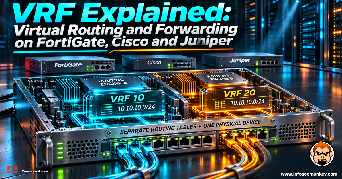
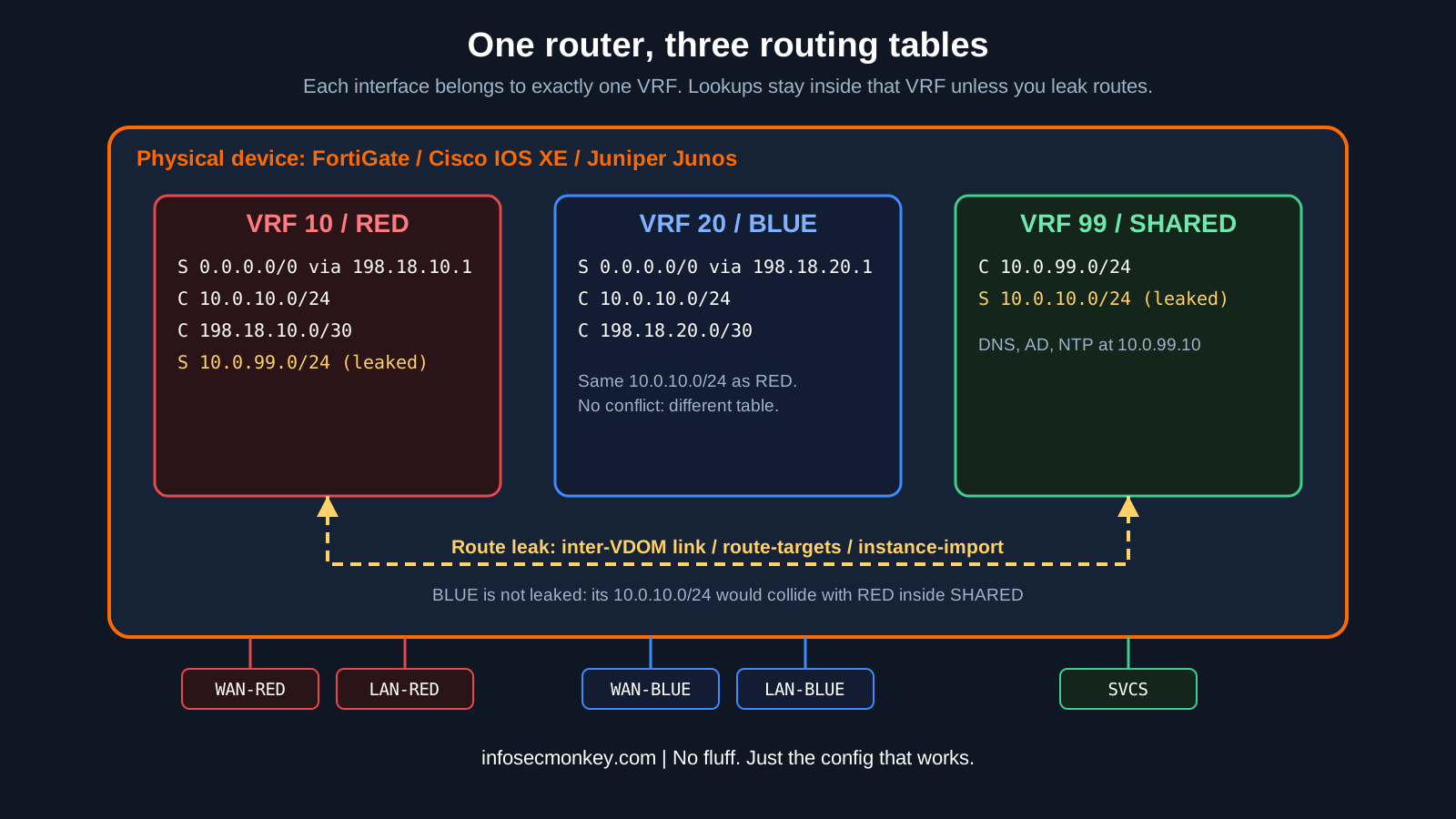
Virtual routing and forwarding splits one physical router or firewall into several independent routing tables. Every layer 3 interface is placed into exactly one VRF. When a packet arrives, the device looks up the destination only in the table that belongs to the ingress interface’s VRF. Routes in one VRF are invisible to the others.
That single rule gives you three things for free:
- Isolation: RED cannot reach BLUE unless you build a path on purpose.
- Overlapping address space: two tenants can both use 10.0.10.0/24 on the same box, because the two prefixes live in different tables.
- Separate default routes: each VRF can exit through its own ISP, tunnel or SD-WAN overlay.
Every device starts with one table, usually called the global or default VRF. You add VRFs as you need them. There are two flavors you will hear about:
- VRF-lite: VRFs on a single device or hop by hop, no MPLS. This is what most enterprise and firewall deployments use and what this post builds.
- MPLS L3VPN: VRFs on provider edge routers with a route distinguisher (RD) to keep overlapping prefixes unique in MP-BGP and route targets (RT) to control which VRF imports what. Same idea, carrier scale.
Figure 1: One device, three VRF routing tables, one deliberate leak
Same concept, three vocabularies
| Item | FortiGate (FortiOS) | Cisco IOS XE | Juniper Junos |
|---|---|---|---|
| What it is called | VRF (numeric ID) | VRF (named) | Routing instance |
| Default table | VRF 0 | Global routing table | inet.0 (master instance) |
| How you create it | set vrf <id> on an interface |
vrf definition <name> |
set routing-instances <name> instance-type virtual-router |
| Interface assignment | set vrf 10 under the interface |
vrf forwarding <name> |
set routing-instances <name> interface <ifl> |
| Show the table | get router info routing-table all |
show ip route vrf <name> |
show route table <name>.inet.0 |
| Ping from a VRF | execute ping-options vrf <id> |
ping vrf <name> <ip> |
ping <ip> routing-instance <name> |
| Common leak method | Inter-VDOM (NPU) links or BGP | Route targets with BGP | instance-import or rib-groups |
VRF vs VDOM vs VLAN
These get confused constantly, especially on FortiGate where both VRFs and VDOMs exist.
| VLAN | VRF | VDOM (FortiGate) | |
|---|---|---|---|
| Layer | Layer 2 segment | Layer 3 routing table | Whole virtual firewall |
| Separates | Broadcast domains | Routes and forwarding | Routing, policies, profiles, admins, logs |
| Overlapping subnets | N/A | Yes | Yes |
| Separate policy set | No | No, one policy table for the VDOM | Yes |
| Overhead | Tiny | Small | Larger, licensing above the model default |
| Use it when | You need a segment | You need separate routing with one security policy owner | You need separate admin domains or tenants |
Rule of thumb: VLANs carry the traffic, VRFs decide where it routes, and VDOMs decide who owns the box. A VLAN subinterface is very often the thing you drop into a VRF.
Where VRFs earn their keep
- Multi-tenant firewalls and MSP edges where customers reuse RFC 1918 space.
- Mergers and acquisitions, where two companies both built on 10.0.0.0/16.
- Guest, IoT or OT networks that must never see a route to production.
- Out-of-band management (Cisco’s Mgmt-vrf, Juniper’s mgmt_junos) so a bad production route cannot cut off SSH.
- SD-WAN segmentation, where each VRF rides the same overlay but stays separate end to end.
Prerequisites and lab architecture
Assumed knowledge: static routing, basic BGP, and how your platform’s firewall policies or ACLs work.
Lab requirements: any one of a FortiGate on FortiOS 7.2 or later (VM is fine), a Cisco IOS XE router (CSR1000v or Catalyst 8000v), or a Juniper vMX or vSRX. Each vendor section stands on its own.
The same design is built on all three platforms: two tenants that deliberately use the same LAN subnet, plus a shared services VRF that only RED is allowed to reach.
| VRF | FortiGate ID | LAN | Uplink (device side) | Next hop |
|---|---|---|---|---|
| RED | 10 | 10.0.10.0/24 (gateway .1) | 198.18.10.2/30 | 198.18.10.1 |
| BLUE | 20 | 10.0.10.0/24 (gateway .1, overlapping on purpose) | 198.18.20.2/30 | 198.18.20.1 |
| SHARED | 99 | 10.0.99.0/24 (gateway .1, DNS at .10) | None | None |
| Role | FortiGate | Cisco IOS XE | Juniper Junos |
|---|---|---|---|
| WAN-RED | port1 | GigabitEthernet1 | ge-0/0/1.0 |
| LAN-RED | port3 | GigabitEthernet2 | ge-0/0/2.0 |
| WAN-BLUE | port2 | GigabitEthernet3 | ge-0/0/3.0 |
| LAN-BLUE | port4 | GigabitEthernet4 | ge-0/0/4.0 |
| SVCS (shared) | port5 | GigabitEthernet5 | ge-0/0/5.0 |
FortiGate VRF configuration
On FortiOS, VRFs are always on. Per the Implementing VRF guide, all routing happens in VRF 0 until you assign a different VRF ID to an interface. There is no separate object to create: the interface’s vrf value is the VRF.
| FortiOS version | VRF IDs per VDOM |
|---|---|
| 6.0 and 6.2 | 0 to 31, CLI only |
| 6.4.2 and later | GUI support added |
| 7.2.1 and later | 0 to 63 |
| 7.2.4 and later | 252 VRFs on non-NP7 models |
| 7.2.9 and later | 252 VRFs on NP7 models |
| 7.6 and later | 0 to 511 |
Version ranges are from Fortinet’s VRF ID configuration article. Also note from the VRF routing support page: VRFs support static routing, OSPF and BGP. Anything else, such as RIP or IS-IS, needs VDOMs instead.
Step 1: Allow overlap and assign interfaces to VRFs
Goal: Put RED, BLUE and SHARED interfaces into VRF 10, 20 and 99, with RED and BLUE using the same LAN subnet.
Action: Enable subnet overlap first. Without it, FortiOS rejects the second 10.0.10.1/24 even though it sits in another VRF.
config system settings
    set allow-subnet-overlap enable
end
config system interface
    edit "port1"
        set vrf 10
        set ip 198.18.10.2 255.255.255.252
        set role wan
    next
    edit "port3"
        set vrf 10
        set ip 10.0.10.1 255.255.255.0
        set allowaccess ping
        set role lan
    next
    edit "port2"
        set vrf 20
        set ip 198.18.20.2 255.255.255.252
        set role wan
    next
    edit "port4"
        set vrf 20
        set ip 10.0.10.1 255.255.255.0
        set allowaccess ping
        set role lan
    next
    edit "port5"
        set vrf 99
        set ip 10.0.99.1 255.255.255.0
        set allowaccess ping
        set role lan
    next
end
GUI verification: Network > Interfaces, click the gear icon on the column header and enable the VRF column. Each port shows its VRF ID.
Step 2: Default routes and policies per VRF
Goal: Give RED and BLUE their own internet exit.
Action: Add one default route per VRF. A static route inherits the VRF of its device, so you do not set vrf here. You only need set vrf on routes with no interface, such as blackhole routes.
config router static
    edit 10
        set gateway 198.18.10.1
        set device "port1"
    next
    edit 20
        set gateway 198.18.20.1
        set device "port2"
    next
end
config firewall policy
    edit 0
        set name "RED-LAN-to-Internet"
        set srcintf "port3"
        set dstintf "port1"
        set action accept
        set srcaddr "all"
        set dstaddr "all"
        set schedule "always"
        set service "ALL"
        set nat enable
    next
    edit 0
        set name "BLUE-LAN-to-Internet"
        set srcintf "port4"
        set dstintf "port2"
        set action accept
        set srcaddr "all"
        set dstaddr "all"
        set schedule "always"
        set service "ALL"
        set nat enable
    next
endStep 3: Leak routes between RED and SHARED
Goal: Let RED reach DNS and AD in SHARED without giving it any route to BLUE.
Action: Connect VRF 10 and VRF 99 with an NPU inter-VDOM link, then add static routes in each direction. As the NP7 hardware acceleration guide explains, single-vdom-npuvlink exposes the npu0_vlink interfaces without enabling multi-VDOM mode, so leaked traffic stays offloaded. Both VLAN subinterfaces use the same VLAN ID and the same subnet, which is why subnet overlap had to be enabled.
config system global
    set single-vdom-npuvlink enable
end
config system interface
    edit "leak10-to-99"
        set vdom "root"
        set vrf 10
        set ip 10.255.10.1 255.255.255.252
        set allowaccess ping
        set interface "npu0_vlink0"
        set vlanid 1010
    next
    edit "leak99-to-10"
        set vdom "root"
        set vrf 99
        set ip 10.255.10.2 255.255.255.252
        set allowaccess ping
        set interface "npu0_vlink1"
        set vlanid 1010
    next
end
config router static
    edit 110
        set dst 10.0.99.0 255.255.255.0
        set gateway 10.255.10.2
        set device "leak10-to-99"
    next
    edit 199
        set dst 10.0.10.0 255.255.255.0
        set gateway 10.255.10.1
        set device "leak99-to-10"
    next
end
config firewall address
    edit "RED-LAN"
        set subnet 10.0.10.0 255.255.255.0
    next
    edit "SHARED-SVCS"
        set subnet 10.0.99.0 255.255.255.0
    next
end
config firewall policy
    edit 0
        set name "RED-to-leak"
        set srcintf "port3"
        set dstintf "leak10-to-99"
        set action accept
        set srcaddr "RED-LAN"
        set dstaddr "SHARED-SVCS"
        set schedule "always"
        set service "DNS" "PING"
    next
    edit 0
        set name "leak-to-SHARED"
        set srcintf "leak99-to-10"
        set dstintf "port5"
        set action accept
        set srcaddr "RED-LAN"
        set dstaddr "SHARED-SVCS"
        set schedule "always"
        set service "DNS" "PING"
    next
end
Static routes are the simplest leak. For dynamic leaking, FortiOS can run BGP across the inter-VDOM link, shown in Fortinet’s route leaking between VRFs with BGP example, and the route leaking between multiple VRFs guide covers a hub VRF design for more than two tables.
GUI verification: Dashboard > Network > Static & Dynamic Routing widget, or Network > Static Routes. The routing monitor shows a VRF column for every entry.
Cisco IOS XE VRF configuration
Modern IOS XE uses the multiprotocol vrf definition and vrf forwarding commands. Per Cisco’s MPLS VPN VRF CLI for IPv4 and IPv6 guide, these replace the older ip vrf and ip vrf forwarding commands, and an upgrade converts the old form automatically. Each address family you want inside the VRF must be enabled explicitly.
Step 4: Define VRFs and assign interfaces
Goal: Create RED, BLUE and SHARED and place the interfaces into them.
Action: Define the VRFs first, then apply vrf forwarding before the IP address on each interface. The EVN command reference documents vrf definition and its sub-modes.
vrf definition RED
 rd 65000:10
 address-family ipv4
 exit-address-family
!
vrf definition BLUE
 rd 65000:20
 address-family ipv4
 exit-address-family
!
vrf definition SHARED
 rd 65000:99
 address-family ipv4
 exit-address-family
!
interface GigabitEthernet1
 vrf forwarding RED
 ip address 198.18.10.2 255.255.255.252
 no shutdown
!
interface GigabitEthernet2
 vrf forwarding RED
 ip address 10.0.10.1 255.255.255.0
 no shutdown
!
interface GigabitEthernet3
 vrf forwarding BLUE
 ip address 198.18.20.2 255.255.255.252
 no shutdown
!
interface GigabitEthernet4
 vrf forwarding BLUE
 ip address 10.0.10.1 255.255.255.0
 no shutdown
!
interface GigabitEthernet5
 vrf forwarding SHARED
 ip address 10.0.99.1 255.255.255.0
 no shutdown
!
ip route vrf RED 0.0.0.0 0.0.0.0 198.18.10.1
ip route vrf BLUE 0.0.0.0 0.0.0.0 198.18.20.1
The RD is optional for pure VRF-lite with static routing, but you need it the moment BGP gets involved, which is the next step.
Step 5: Leak routes with route targets
Goal: Import SHARED’s subnet into RED and RED’s subnet into SHARED.
Action: Add route targets to the VRFs and let a local BGP process do the import. No BGP neighbor is required: the BGP process alone handles local import between VRFs. Redistribute only connected routes so RED’s default route does not leak into SHARED.
vrf definition RED
 address-family ipv4
  route-target export 65000:10
  route-target import 65000:10
  route-target import 65000:99
 exit-address-family
!
vrf definition SHARED
 address-family ipv4
  route-target export 65000:99
  route-target import 65000:99
  route-target import 65000:10
 exit-address-family
!
router bgp 65000
 bgp log-neighbor-changes
 address-family ipv4 vrf RED
  redistribute connected
 exit-address-family
 !
 address-family ipv4 vrf SHARED
  redistribute connected
 exit-address-family
BLUE never imports 65000:99, so it stays fully isolated. Add ACLs or a zone-based firewall on the SHARED interface if you need to restrict which ports RED can reach.
Juniper Junos VRF configuration
Junos calls a VRF a routing instance. According to the routing instances overview, the virtual-router type is the non-VPN cousin of the vrf type and has no RD, route target or vrf-import and vrf-export requirements. That makes it the right choice for VRF-lite. Use instance-type vrf only when you are building an MPLS L3VPN.
Step 6: Create routing instances
Goal: Create RED, BLUE and SHARED virtual routers with their own default routes.
Action: Configure the interface addresses normally, then attach each logical interface to an instance. The virtual-router configuration guide lists the protocols supported inside the instance: static, BGP, OSPF, IS-IS, RIP, LDP and PIM.
set interfaces ge-0/0/1 unit 0 family inet address 198.18.10.2/30
set interfaces ge-0/0/2 unit 0 family inet address 10.0.10.1/24
set interfaces ge-0/0/3 unit 0 family inet address 198.18.20.2/30
set interfaces ge-0/0/4 unit 0 family inet address 10.0.10.1/24
set interfaces ge-0/0/5 unit 0 family inet address 10.0.99.1/24
edit routing-instances RED
set instance-type virtual-router
set interface ge-0/0/1.0
set interface ge-0/0/2.0
set routing-options static route 0.0.0.0/0 next-hop 198.18.10.1
top
edit routing-instances BLUE
set instance-type virtual-router
set interface ge-0/0/3.0
set interface ge-0/0/4.0
set routing-options static route 0.0.0.0/0 next-hop 198.18.20.1
top
edit routing-instances SHARED
set instance-type virtual-router
set interface ge-0/0/5.0
top
commit check
commit
Each instance gets its own table named after it: RED.inet.0, BLUE.inet.0 and SHARED.inet.0.
Step 7: Leak routes with instance-import
Goal: Import exactly one prefix in each direction between RED and SHARED.
Action: Write a policy that matches the other instance and the prefix you want, then apply it with instance-import. This is the same pattern the Juniper community uses in this instance-import example. The older alternative is rib-groups, which copy routes between tables and can be filtered with an import-policy, as shown in this rib-group leaking thread.
edit policy-options policy-statement SHARED-TO-RED
set term svcs from instance SHARED
set term svcs from route-filter 10.0.99.0/24 exact
set term svcs then accept
set term deny then reject
top
edit policy-options policy-statement RED-TO-SHARED
set term lan from instance RED
set term lan from route-filter 10.0.10.0/24 exact
set term lan then accept
set term deny then reject
top
set routing-instances RED routing-options instance-import SHARED-TO-RED
set routing-instances SHARED routing-options instance-import RED-TO-SHARED
commit
On an SRX, routing instances do not replace security zones. RED-to-SHARED traffic still needs the interfaces in zones and a security policy between them.
Verification and validation
FortiGate
get router info routing-table all
execute ping-options vrf 10
execute ping 10.0.99.10
execute ping-options reset
Expected success output: each VRF prints its own table, the leaked prefix appears only in VRF 10 and VRF 99, and the ping from VRF 10 to 10.0.99.10 gets replies. The vrf option is listed under execute ping-options in Fortinet’s ping-options article.
Routing table for VRF=10
S*      0.0.0.0/0 [10/0] via 198.18.10.1, port1, [1/0]
C       10.0.10.0/24 is directly connected, port3
S       10.0.99.0/24 [10/0] via 10.255.10.2, leak10-to-99, [1/0]
C       10.255.10.0/30 is directly connected, leak10-to-99
C       198.18.10.0/30 is directly connected, port1

Routing table for VRF=20
S*      0.0.0.0/0 [10/0] via 198.18.20.1, port2, [1/0]
C       10.0.10.0/24 is directly connected, port4
C       198.18.20.0/30 is directly connected, port2

Routing table for VRF=99
S       10.0.10.0/24 [10/0] via 10.255.10.1, leak99-to-10, [1/0]
C       10.0.99.0/24 is directly connected, port5
C       10.255.10.0/30 is directly connected, leak99-to-10
Cisco IOS XE
show vrf
show ip route vrf RED
ping vrf RED 10.0.99.10 source GigabitEthernet2
Name Default RD Protocols Interfaces
BLUE 65000:20 ipv4 Gi3
Gi4
RED 65000:10 ipv4 Gi1
Gi2
SHARED 65000:99 ipv4 Gi5
Routing Table: RED
S* 0.0.0.0/0 [1/0] via 198.18.10.1
C 10.0.10.0/24 is directly connected, GigabitEthernet2
B 10.0.99.0/24 is directly connected, 00:02:11, GigabitEthernet5The B entry for 10.0.99.0/24 pointing at GigabitEthernet5 is the leak working. show ip route vrf BLUE should show no 10.0.99.0/24 at all.
Juniper Junos
show route table RED.inet.0
show route table BLUE.inet.0
ping 10.0.99.10 routing-instance RED count 3
RED.inet.0: 6 destinations, 6 routes (6 active, 0 holddown, 0 hidden)
+ = Active Route, - = Last Active, * = Both
0.0.0.0/0 *[Static/5] 00:04:20
> to 198.18.10.1 via ge-0/0/1.0
10.0.10.0/24 *[Direct/0] 00:04:20
> via ge-0/0/2.0
10.0.99.0/24 *[Direct/0] 00:01:05
> via ge-0/0/5.0Troubleshooting and gotchas
1. The overlap trap when you leak
Overlapping subnets are fine until two of them need the same shared service. SHARED can only hold one route to 10.0.10.0/24, so if you leak both RED and BLUE into it, return traffic goes to whichever one wins. Leak one, or source NAT the second tenant into a unique range on the way in.
config firewall ippool
    edit "BLUE-to-SHARED"
        set startip 10.255.20.10
        set endip 10.255.20.10
    next
end
Apply the pool with set nat enable and set ippool enable on the BLUE leak policy, and route 10.255.20.10/32 back toward BLUE’s leak link in VRF 99.
2. Cisco wipes your IP when you add the VRF
Applying vrf forwarding RED to an interface that already has an address removes the IPv4 address, and IOS XE prints a message saying so. This is the number one cause of “I added the VRF and the link died” during change windows.
show running-config interface GigabitEthernet2
show ip interface brief vrf RED
Fix: always configure vrf forwarding first, then the ip address. When changing a live interface, paste both lines together in the same change.
3. Pings and management traffic use the wrong table
A plain ping from the CLI uses the default table on all three platforms, so it fails even when the VRF is healthy. Use execute ping-options vrf 10 on FortiGate, ping vrf RED on Cisco and routing-instance RED on Junos. The same applies to services the box originates itself. On FortiGate, local-out traffic such as DNS, NTP and FortiGuard defaults to VRF 0. Newer FortiOS releases let you pick a VRF ID for local-out traffic, documented in Support specific VRF ID for local-out traffic.
diagnose sniffer packet any 'host 10.0.99.10' 4 0 l
diagnose debug flow filter addr 10.0.99.10
diagnose debug flow trace start 10
diagnose debug enable
If the flow trace shows reverse path check fail or no route, the leak is missing a return route in the other VRF.
Sources
- Fortinet: Implementing VRF (FortiOS 7.6.5 Administration Guide)
- Fortinet Community: Technical Tip, Virtual routing and forwarding ID configuration
- Fortinet: VRF routing support (FortiOS 7.4.9 Administration Guide)
- Fortinet: Route leaking between multiple VRFs (FortiOS 7.6.7 Administration Guide)
- Fortinet: Enabling NP7 inter-VDOM links to accelerate VRF route leaking
- Fortinet: Route leaking between VRFs with BGP (FortiOS 7.2.2)
- Fortinet: Support specific VRF ID for local-out traffic (FortiOS 8.0)
- Fortinet Community: execute ping-options reference including the vrf option
- Cisco: MPLS VPN VRF CLI for IPv4 and IPv6 VPNs (vrf definition and vrf forwarding)
- Cisco: IOS Easy Virtual Network Command Reference, vrf definition
- Juniper: Routing Instances Overview
- Juniper: Configuring Virtual-Router Routing Instances
- Juniper Community: Route leaking between VRFs using RIB groups
- Juniper Community: Leaking routes from a virtual-router instance with instance-import