If you've spent any time configuring user authentication on... Full Story
By Manny Fernandez
March 9, 2019
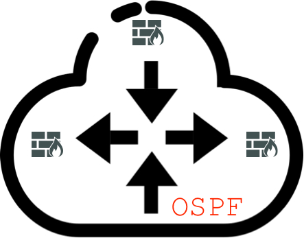
Configuring OSPF on Fortigate
The Fortigate is capable of doing OSPF, BGP, and RIP from a dynamic routing protocol perspective. It is pretty straight forward and if you know Cisco and OSPF, you will be more than fine in the Fortigate world.
Lets get started.
Scenario:
(1) FortiWiFi 51E -
loopback1 - 5.5.5.5/32
lan - 10.4.31.0/24
lan5 - 10.2.2.10/24

(1) Fortigate 140E
loopback1 - 4.4.4.4/32
loopback2 - 5.5.5.6/32
loobback3 - 6.6.6.6/32
port37 - 10.2.2.20/24
Objectives:
* Establish OSPF adjacencies
* From 140E, I want to redistribute only loopback2 which is a connected route but NOT loopback3 which is also a connected route.
Requirements
* Ensure Advanced Routing is enabled under the System, Visibility section of the Fortigate.
* Have connectivity between the 51E and the 140E
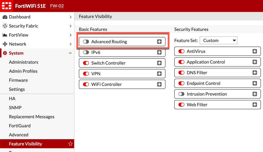
To enabled the Advanced Routing on the Fortigate, Go to System, Feature Visibility and turn on the Advanced Routing section.
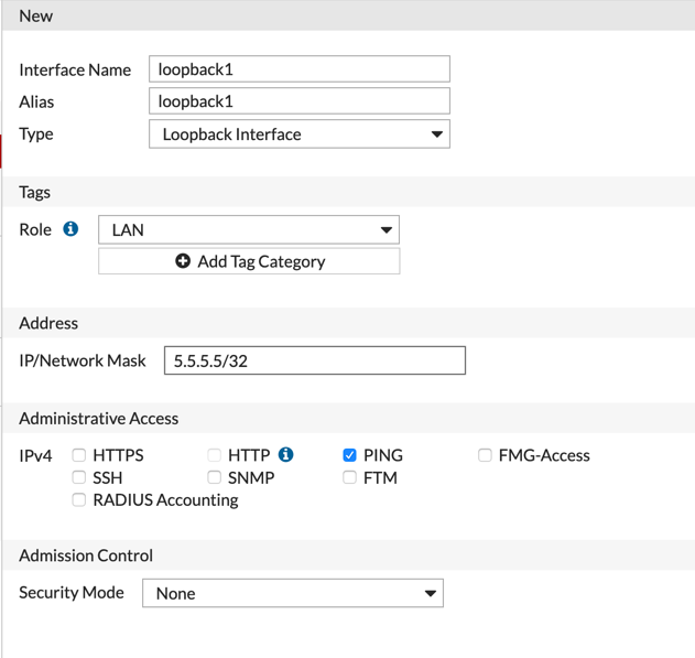
We need to create a loopback interface. Go to Network, Interfaces and select Create New. Once in there, select the drop down next to the VLAN selection and change it to loopback interface. Assign an IP address (normally it is a /32 address).
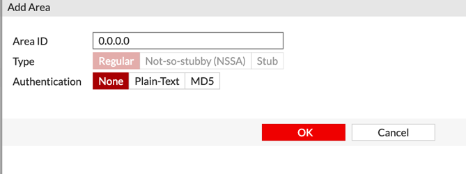
Next we will create the area. In this example, it is area 0. In our example, we are NOT using Auth for the OSPF. I recommend that you consider this when deploying in your environment.

Now, we will create the interface that will be the OSPF connection.
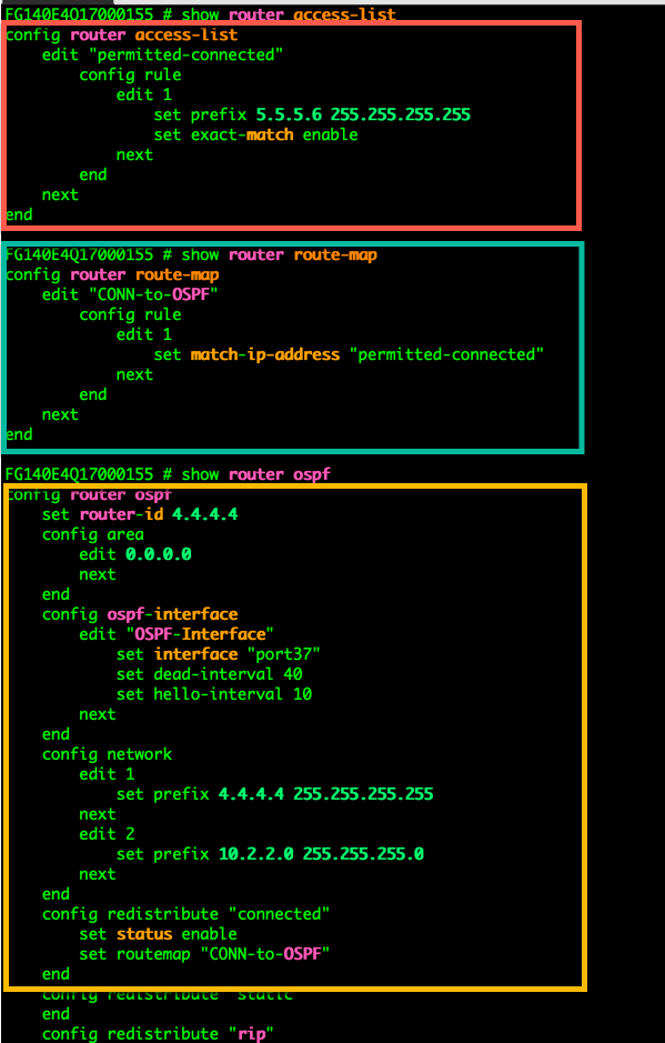
Now on the command line, we will configure an access-list that will be used to match traffic, a route-map that references the access-list and then tell OSPF to redistribute ‘connected’ routes.
Configuring the Access-List
config router access-list
   edit "permitted-connected"
      config rule
          edit 1
             set prefix 5.5.5.6 255.255.255.255
             set exact-match enable
          next
       end
      next
end
Next we will configure the route-map
config router route-map
    edit "CONN-to-OSPF"
       config rule
          edit 1
             set match-ip-address "permitted-connected"
         next
        end
    next
end
Now, we will apply the route-map to the ‘redistribution of connected’ section of the OSPF process
config router ospf
   config redistribute "connected"
       set status enable
       set routemap "CONN-to-OSPF"
    end
Routing Table

On the 51E, we can now see that the 51E is learning the 5.5.5.6/32 route which is the loopback2 IP address. We can see that we did NOT learn loopback3 of the 140E because it is not defined in the access-list therefore it does not match.
OSPF Neighbor States
Down – Down is the starting state for all OSPF routers. A start event, such as configuring the protocol, transitions the router to the Init state. The local router may list a neighbor in this state when no hello packets have been received within the specified router dead interval for that interface.
Init – The Init state is reached when an OSPF router receives a hello packet but the local router ID is not listed in the received Neighbor field. This means that bidirectional communication has not been established between the peers.
Attempt – The Attempt state is valid only for Non-Broadcast Multi-Access (NBMA) networks. It means that a hello packet has not been received from the neighbor and the local router is going to send a unicast hello packet to that neighbor within the specified hello interval period.
2-Way. –The 2-Way state indicates that the local router has received a hello packet with its own router ID in the Neighbor field. Thus, bidirectional communication has been established and the peers are now OSPF neighbors.
ExStart – In the ExStart state, the local router and its neighbor establish which router is in charge of the database synchronization process. The higher router ID of the two neighbors controls which router becomes the master.
Exchange – In the Exchange state, the local router and its neighbor exchange DD packets that describe their local databases.
Loading – Should the local router require complete LSA information from its neighbor, it transitions to the Loading state and begins to send link-state request packets.
Full – The Full state represents a fully functional OSPF adjacency, with the local router having received a complete link-state database from its peer. Both neighboring routers in this state add the adjacency to their local database and advertise the relationship in a link-state update packet.
OSPF Packet Types
Regardless of the OSPF packet type, they all share a 24 byte header. This allows the receiving device to process and validate the receiving packet.
Version – The first field is the ‘version’. OSPF has two version in use today; version 2 (RFC2328) which is used with IPv4, and version 3 (RFC 5340) which is used with IPv6.
Type – The type field is one of five different types:
- Hello Packet
- Database Description Packet
- Link State Request Packet
- Link State Update Packet
- Link State Acknowledge Packet
Packet Length – This is the length of the OSPF packet type which is 2 Bytes.
Router ID – The advertising device’s Router ID. This is configurable on each device.
Area ID – The area, is a 32 bit ID. The area ID is assigned to the sending device’s interface sending the OSPF packet.
Checksum – This is a standard IP checksum. It does NOT include the authentication Field which is 2 bytes.
AuType – What Authentication type are you using (normally 2-bytes). The authentication types are either no password (0), clear text (1) or MD5 (2).
OSPF Debugging Commands
diagnose ip router ospf level info

diagnose ip router ospf all enable

diagnose debug enable
Make sure you disable these debugs since it will not do it automatically.
Recent posts
-

-

DNS is one of those technologies that quietly underpins... Full Story
-

BGP issues on FortiGate firewalls usually trace back to... Full Story
-

Every time your laptop talks to your router, a... Full Story
-

If you've spent any time configuring NAT on a... Full Story
-

If you have spent any time configuring firewall policies... Full Story
-

High availability on FortiGate is one of those features... Full Story
-

If you've configured SD-WAN on a FortiGate, you've almost... Full Story
-

FortiLink is the management protocol that turns a FortiSwitch... Full Story
-

FortiSwitches are pretty rock solid from Mean Time Between... Full Story
-

This is a quicky tip. Have you ever gone... Full Story
-

DNS is one of those quiet pieces of internet... Full Story
-

This article is an updated version of the previous... Full Story
-

You will add ns2 as a secondary (slave) BIND9... Full Story
-

In the process of deploying my lab, I needed... Full Story
-

RFC 8805, used to be known as Self-Correcting IP... Full Story
-

Years back, I wrote an article about certificate pinning. ... Full Story
-

FortiGates have the ability to send alerts to Microsoft... Full Story
-

In this post, I am going to walk through... Full Story
-

Troubleshooting VoIP on a FortiGate can feel like trying... Full Story
-

Prior to FortiOS 7.0, there were three commands to... Full Story
-

In this post, I am going to go over... Full Story
-

What we are going to do: We are going... Full Story
-

Choosing between FGCP (FortiGate Clustering Protocol) and FGSP (FortiGate... Full Story
-

Creating a VLAN on macOS (The "Pro" Move) A... Full Story
-

This blog post explores the logic behind how macOS... Full Story
-

Pretty Fly for a Wi-Fi Tell My Wi-Fi Love... Full Story
-

Part of my daily gig is creating BoMs (Bill-of-Materials)... Full Story
-

ICMP introduces several security risks, but careful filtering, rate... Full Story
-

The command diag debug application dhcps -1 enables full... Full Story
-

In the world of FortiOS, execute tac report is... Full Story
-

LLDP; What is it The Link Layer Discovery Protocol... Full Story
-

What it actually does When you run diagnose fdsm... Full Story
-

Monkey Bites are bite-sized, high-impact security insights designed for... Full Story
-

I have run macOS in macOS with Parallels but... Full Story
-

Don't be confused with my other FortiNAC posts where... Full Story
-

This is the third session in a multi-part article... Full Story
-

Today I was configuring key-based authentication on a FortiGate... Full Story
-

Netcat, often called the "Swiss Army knife" of networking,... Full Story
-

At its core, IEEE 802.1X is a network layer... Full Story
-

In case you did not see the previous FortiNAC... Full Story
-

This is our 5th session where we are going... Full Story
-

Now that we have Wireshark installed and somewhat configured,... Full Story
-

The Philosophy of Packet Analysis Troubleshooting isn't about looking... Full Story
-

1. Executive Summary Objective This guide walks through the... Full Story
-

If you have ever tried to stand up a... Full Story
-

1. Executive Summary Objective This guide takes the FortiGate... Full Story