If you've spent any time configuring user authentication on... Full Story
By Manny Fernandez
May 1, 2019

Perimeter Switch Configuration with Fortiswitch (Non-Fortilink)
One of the designs I normally do for customers when they purchase Highly Available firewalls is HA perimeter switches. When using Fortiswitches, you can easily configure the switches with Fortilink which is integrated into the Fortigate GUI and as such can be managed via the GUI or via FortiManager (Centralized Manager). However in this quick post, I am going to use a pair of 108E POE Fortiswitches in stand-alone mode to configure them as perimeter Layer 2 switches handling multiple ISPs and multiple Fortigate Firewalls. Below is a moch up diagram of what something like this would look like.
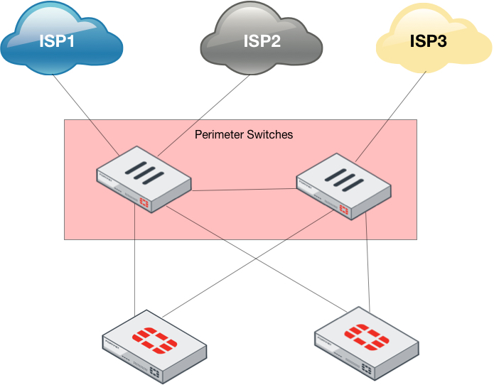
In the above scenario, I am configuring three ISPs. I will show how you can configure the following scenarios:
Scenario One – You will consume three ports on each Fortigate and three ports on each Fortiswitch. Each port on the switch will be an access port with 1-8 ports in a “trunk” (or port-channel for you Cisco folks) that is passing the different VLANs that you create.
Scenario Two – In this scenario, the Fortigates will have a single (or multiple in LAG or 802.3ad) 802.1q trunk port that passes all three ISP VLANs and each Fortigate will have multiple VLANs under the single physical (or LAG) port.
Either way, the switch configuration will have similarities and I will point them out.
First thing you should do is upgrade these switches to the 6.x code release.
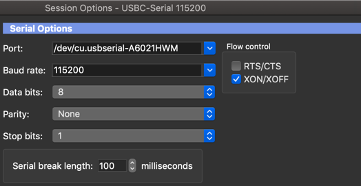
NOTE: To console into these switches, you need to set the speed to 115200
Configuring the VLANs
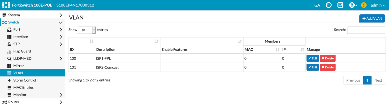
We will now create VLANs for each ISP. In my scenario, I have FPL, AT&T and Comcast using VLANs 100, 101, and 102 respectively.
Above you can see I have already created two VLANs. This configuration is accessible via the ‘Switch’, ‘VLAN’ section of the switch GUI.

On the top right hand side of the ‘VLAN’ section, you need to click the ‘Add VLAN’ button.
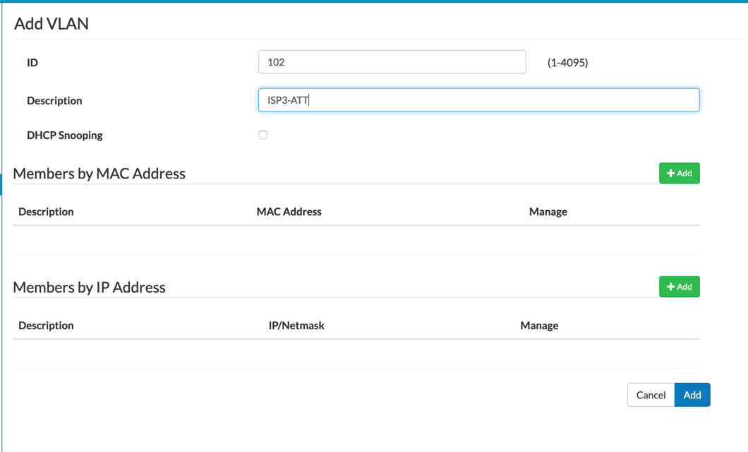
Next you will add the VLAN ID under the ‘ID’ field. Give it a description. If you have read my blog posts before, I always say to use something meaningful. You can leave the rest default for now and click ‘Add’.
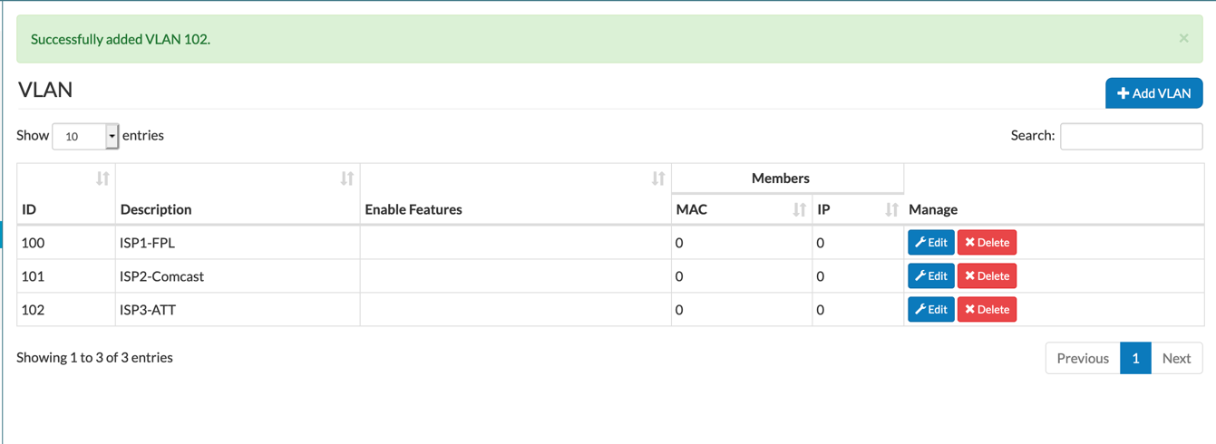
Now we can see that we have three VLANs 100 for FPL, 101 for Comcast and 102 for AT&T.
Configuring the Ports
Although I configured three physical ports using VLAN 100, 101, and 102, the goal of this configuration is to have different ISPs configured across different switches in case of a switch failure. Maybe have ISP1 (the primary) and ISP3 (the tertiary) on one switch and ISP2 (the secondary) on the other switch.
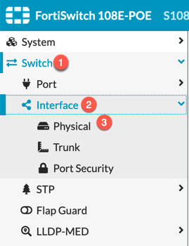
To configure the switch ports, go to ‘Switch’ then ‘Interface’ and the ‘Physical’
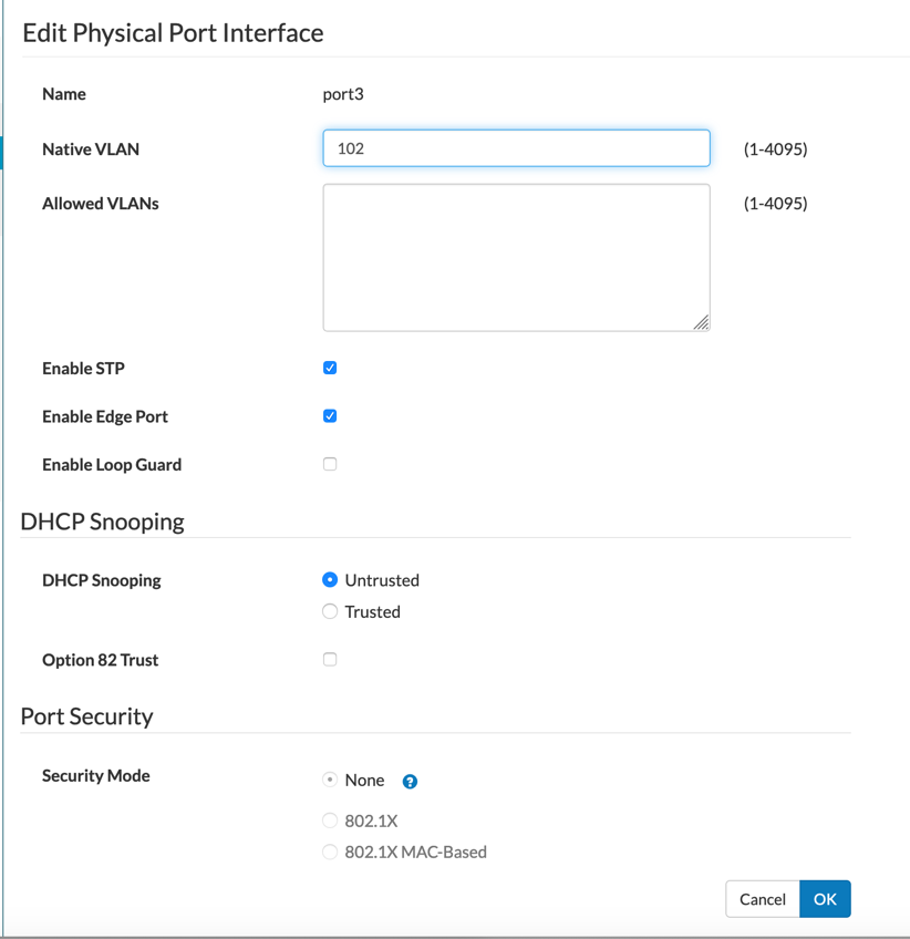
For the access-layer switch ports, set the ‘Native VLAN’ to whatever you want the VLAN ID to be.
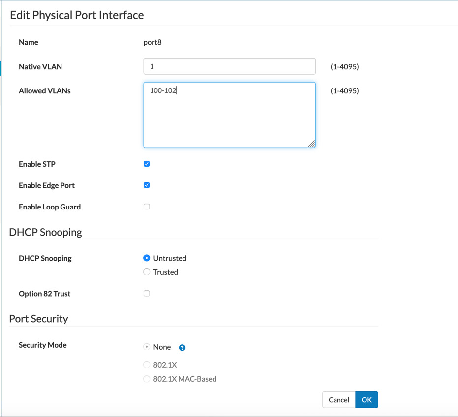
I am using port 8 of the switches as a trunk port between the two perimeter switches. As you can see above. You can set the ‘Native VLAN’ to anything you want but the ‘Allowed VLANs’ sections needs to contain the multiple VLANs you created above (in our case 100, 101, and 102).
From the command line, we can see the physical access ports configured as well as the ‘tagged’ (802.1q) port.
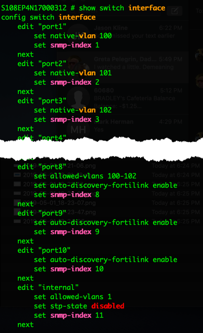
You can view this by entering the following command:
show switch interface
We can also see the VLANs
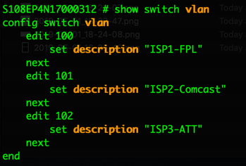
This can be seen using the following command:
show switch vlan
Hope this helps.
Recent posts
-

-

DNS is one of those technologies that quietly underpins... Full Story
-

BGP issues on FortiGate firewalls usually trace back to... Full Story
-

Every time your laptop talks to your router, a... Full Story
-

If you've spent any time configuring NAT on a... Full Story
-

If you have spent any time configuring firewall policies... Full Story
-

High availability on FortiGate is one of those features... Full Story
-

If you've configured SD-WAN on a FortiGate, you've almost... Full Story
-

FortiLink is the management protocol that turns a FortiSwitch... Full Story
-

FortiSwitches are pretty rock solid from Mean Time Between... Full Story
-

This is a quicky tip. Have you ever gone... Full Story
-

DNS is one of those quiet pieces of internet... Full Story
-

This article is an updated version of the previous... Full Story
-

You will add ns2 as a secondary (slave) BIND9... Full Story
-

In the process of deploying my lab, I needed... Full Story
-

RFC 8805, used to be known as Self-Correcting IP... Full Story
-

Years back, I wrote an article about certificate pinning. ... Full Story
-

FortiGates have the ability to send alerts to Microsoft... Full Story
-

In this post, I am going to walk through... Full Story
-

Troubleshooting VoIP on a FortiGate can feel like trying... Full Story
-

Prior to FortiOS 7.0, there were three commands to... Full Story
-

In this post, I am going to go over... Full Story
-

What we are going to do: We are going... Full Story
-

Choosing between FGCP (FortiGate Clustering Protocol) and FGSP (FortiGate... Full Story
-

Creating a VLAN on macOS (The "Pro" Move) A... Full Story
-

This blog post explores the logic behind how macOS... Full Story
-

Pretty Fly for a Wi-Fi Tell My Wi-Fi Love... Full Story
-

Part of my daily gig is creating BoMs (Bill-of-Materials)... Full Story
-

ICMP introduces several security risks, but careful filtering, rate... Full Story
-

The command diag debug application dhcps -1 enables full... Full Story
-

In the world of FortiOS, execute tac report is... Full Story
-

LLDP; What is it The Link Layer Discovery Protocol... Full Story
-

What it actually does When you run diagnose fdsm... Full Story
-

Monkey Bites are bite-sized, high-impact security insights designed for... Full Story
-

I have run macOS in macOS with Parallels but... Full Story
-

Don't be confused with my other FortiNAC posts where... Full Story
-

This is the third session in a multi-part article... Full Story
-

Today I was configuring key-based authentication on a FortiGate... Full Story
-

Netcat, often called the "Swiss Army knife" of networking,... Full Story
-

At its core, IEEE 802.1X is a network layer... Full Story
-

In case you did not see the previous FortiNAC... Full Story
-

This is our 5th session where we are going... Full Story
-

Now that we have Wireshark installed and somewhat configured,... Full Story
-

The Philosophy of Packet Analysis Troubleshooting isn't about looking... Full Story
-

Have you ever wanted to do some testing on... Full Story
-

Ask ten engineers to define "a network" and you... Full Story
-

1. Executive Summary Objective: This guide turns a FortiAuthenticator... Full Story