If you've spent any time configuring user authentication on... Full Story
By Manny Fernandez
September 3, 2019

VPN Hair-Pinning on Fortigate Firewalls
Here is an issue I get questions about all the time.
Use Case
Customer has two VPNs.
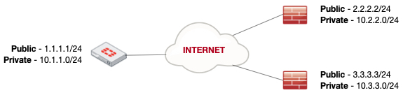
Customer wants to get traffic from 10.3.3.0/24 (spoke 2) to 10.2.2.0/24 (spoke 1) using the Fortigate as the hub. Currently, there each spoke has a site-to-site VPN already established.
Usually customers running Checkpoint have a difficult time understanding the concept because normally, Checkpoint is a strict Policy-based VPN solution. They DO have route-based VPN capabilities, but you would be hard-pressed to even find Checkpoint employees that have mastered or use this feature. It is called VTI or Virtual Tunnel Interfaces. In case you are interested in VTI, here is a link. Cisco ASA is also Policy-Based VPN so it suffers from the same limitation. As for Fortigate, PaloAlto, Juniper and even SonicWall, Route-based VPNs are readily available.
Configuration
Here we go:
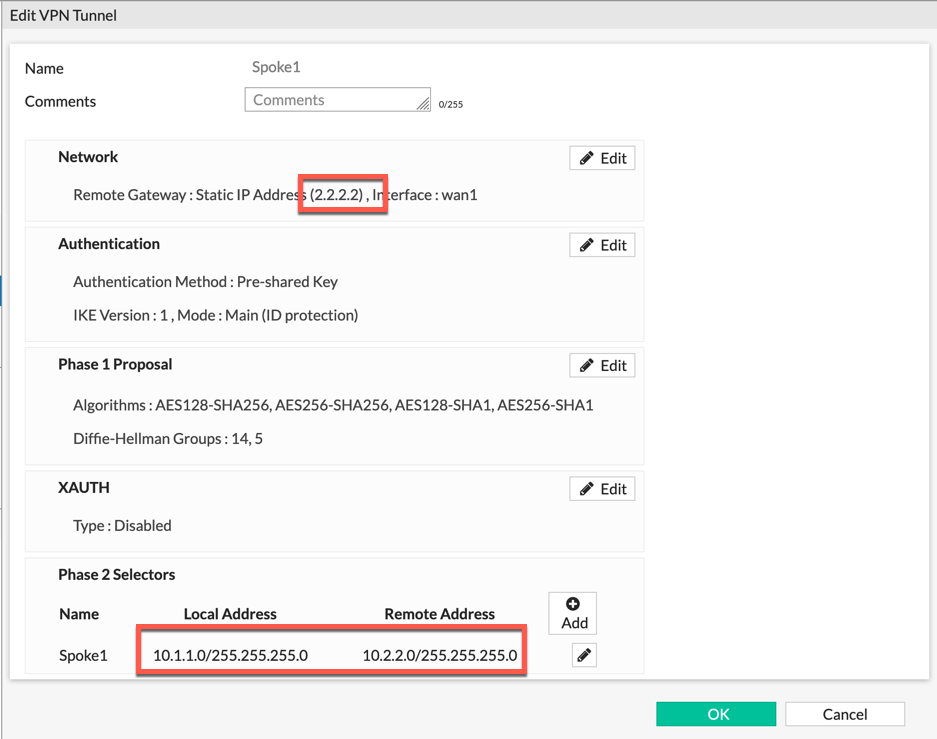
Here we can see that we have the Site-to-Site VPN to Spoke 1 and we can see that the Phase II Selector shows Local Address of 10.1.1.0/24 to Remote Address 10.2.2.0/24 and the peer IP is 2.2.2.2

On this screenshot, we have our Site-to-Site VPN to Spoke 2 and we can see that the Phase II selector shows Local Address of 10.1.1.0/24 to Remote Address 10.3.3.0/24 and the peer IP is 3.3.3.3
Now we are showing the IPv4 Policies showing the access from Spoke2 to port2 (Inside) and the same with Spoke1.
In our requirement, we need to get traffic from 10.3.3.0/24 to 10.2.2.0/24 using the 10.1.1.0/24 as the hub.

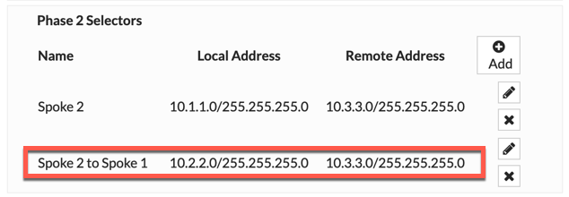
You will need to add 10.3.3.0/24 as a “LOCAL” address to the VPN going to 10.2.2.0/24 . This is because the firewall needs to know that this new traffic will be considered as Interesting Traffic and as such will encrypt it the proper IPsec VPN.
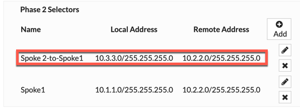
Here we can see the Spoke 2 - to - Spoke 1 Phase II selector completed with the additional networks.
This is the the Spoke 2 VPN Phase II selectors with the additional networks.
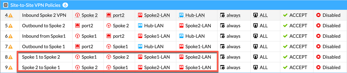
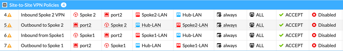
Now we can see that a policy to permit traffic from Spoke 2 to Spoke 1 and Spoke 1 to Spoke 2 is needed. Pay particular attention to the Source and Destination Interfaces.
Remember, if you are using Central NAT you will need to add a Spoke1 to Spoke2 with NAT Disabled and the same in reverse.
Other Options
Option 1
ADVPN – Using AD VPN, you will be able to have Spoke 2 bring up a dynamic VPN tunnel between Spoke 2 and Spoke 1 and the reverse would be true as well. In this configuration, you would use BGP internally to learn routes that leave at each spoke.
Option 2
Quad Zeros – Instead of defining the Phase II selectors with specific IP addresses, you could set Phase II selectors to 0.0.0.0/0 on the local side, and 0.0.0.0/0 on the remote side. Then you can use routing (either static or dynamic) to route traffic accordingly. Remember that the VPN tunnel interfaces use a 0.0.0.0 address because it is unnumbered, but you CAN assign an IP address to the tunnel interface and configure routing inside the tunnel (e.g. OSPF).
Hope this helps.
Recent posts
-

-

DNS is one of those technologies that quietly underpins... Full Story
-

BGP issues on FortiGate firewalls usually trace back to... Full Story
-

Every time your laptop talks to your router, a... Full Story
-

If you've spent any time configuring NAT on a... Full Story
-

If you have spent any time configuring firewall policies... Full Story
-

High availability on FortiGate is one of those features... Full Story
-

If you've configured SD-WAN on a FortiGate, you've almost... Full Story
-

FortiLink is the management protocol that turns a FortiSwitch... Full Story
-

FortiSwitches are pretty rock solid from Mean Time Between... Full Story
-

This is a quicky tip. Have you ever gone... Full Story
-

DNS is one of those quiet pieces of internet... Full Story
-

This article is an updated version of the previous... Full Story
-

You will add ns2 as a secondary (slave) BIND9... Full Story
-

In the process of deploying my lab, I needed... Full Story
-

RFC 8805, used to be known as Self-Correcting IP... Full Story
-

Years back, I wrote an article about certificate pinning. ... Full Story
-

FortiGates have the ability to send alerts to Microsoft... Full Story
-

In this post, I am going to walk through... Full Story
-

Troubleshooting VoIP on a FortiGate can feel like trying... Full Story
-

Prior to FortiOS 7.0, there were three commands to... Full Story
-

In this post, I am going to go over... Full Story
-

What we are going to do: We are going... Full Story
-

Choosing between FGCP (FortiGate Clustering Protocol) and FGSP (FortiGate... Full Story
-

Creating a VLAN on macOS (The "Pro" Move) A... Full Story
-

This blog post explores the logic behind how macOS... Full Story
-

Pretty Fly for a Wi-Fi Tell My Wi-Fi Love... Full Story
-

Part of my daily gig is creating BoMs (Bill-of-Materials)... Full Story
-

ICMP introduces several security risks, but careful filtering, rate... Full Story
-

The command diag debug application dhcps -1 enables full... Full Story
-

In the world of FortiOS, execute tac report is... Full Story
-

LLDP; What is it The Link Layer Discovery Protocol... Full Story
-

What it actually does When you run diagnose fdsm... Full Story
-

Monkey Bites are bite-sized, high-impact security insights designed for... Full Story
-

I have run macOS in macOS with Parallels but... Full Story
-

Don't be confused with my other FortiNAC posts where... Full Story
-

This is the third session in a multi-part article... Full Story
-

Today I was configuring key-based authentication on a FortiGate... Full Story
-

Netcat, often called the "Swiss Army knife" of networking,... Full Story
-

At its core, IEEE 802.1X is a network layer... Full Story
-

In case you did not see the previous FortiNAC... Full Story
-

This is our 5th session where we are going... Full Story
-

Now that we have Wireshark installed and somewhat configured,... Full Story
-

The Philosophy of Packet Analysis Troubleshooting isn't about looking... Full Story
-

Have you ever wanted to do some testing on... Full Story
-

Ask ten engineers to define "a network" and you... Full Story
-

1. Executive Summary Objective: This guide turns a FortiAuthenticator... Full Story