If you've spent any time configuring user authentication on... Full Story
By Manny Fernandez
September 1, 2018

IKEv2 Dynamic Remote Fortigate to Head-In ASA
Customer had a Cisco ASA 5516-X that we used to replace aging 5510’s. I told the customer that we would ONLY do IKEv2 on this set of firewalls as I did not want to put old technology on a “new” platform. Customer was running EZ-VPN on 5510 and wanted to replace their End-of-Life ASA 5505. Customer purchased 6 Fortigate 50Es for the remotes as a starting point. These firewalls were behind NAT’d devices inside hospitals around the country.
In the past, when the customer had ASA 5505s at the remote sites, the only way to connect to them was when traffic was initiated from the 5505 to the main site. This was a problem sometimes. With the new Fortigate, this problem was solved. Using FortiCloud, the firewalls build a management tunnel to the Forticloud environment upon connecting to an Internet connection. You can then log into the FortiCloud Portal and ride that management tunnel back to the Fortigate to manage it.
This configuration CAN be done entirely via the GUI, however I decided to do this one via the CLI.
Here goes it:
config firewall address
         edit "LOCAL-LAN"
                set color 18
               set subnet 10.12.18.0 255.255.255.0
         next
        edit "REMOTE-LAN-01"
               set color 18
               set allow-routing enable
               set subnet 10.11.0.0 255.255.0.0
          next
         edit "REMOTE-LAN-02"
               set color 18
               set allow-routing enable
               set subnet 10.10.0.0 255.255.0.0
           next
end
This creates the address objects I will use as the Phase II selectors in the VPN.
config vpn ipsec phase1-interface
        edit "HEAD-IN"
                   set interface "wan1"
                   set ike-version 2
                   set peertype any
                   set proposal aes256-sha1
                   set localid "remotesite@customer.remote"
                   set remote-gw 1.1.1.1
                   set psksecret %Pre-Shared-Key-Here%
            next
end
Here we can see the creation of the Phase I of the VPN. We can see that it is using IKE v2. The real information has been changed to protect the guilty 🙂
config vpn ipsec phase2-interface
         edit "18 to 10.11"
                 set phase1name "HEAD-IN"
                 set proposal aes256-sha256
                 set src-addr-type name
                 set dst-addr-type name
                 set src-name "LOCAL-LAN"
                 set dst-name "REMOTE-LAN-01"
            next
            edit "18 to 10.10"
                 set phase1name "HEAD-IN"
                 set proposal aes256-sha256
                 set src-addr-type name
                 set dst-addr-type name
                 set src-name "LOCAL-LAN"
                 set dst-name "REMOTE-LAN-02"
              next
end
Here you can see the Phase II selectors we are going to use. We can see that we are using AES-256 with a SHA-256 hash. We can also see we used ‘src-name’ to choose the address object we created earlier.
config firewall policy
         edit 4
                 set name "VPN 18 to RAM"
                 set srcintf "lan"
                 set dstintf "HEAD-IN"
                 set srcaddr "LOCAL-LAN"
                 set dstaddr "REMOTE-LAN-01" "REMOTE-LAN-02"
                 set action accept
                 set schedule "always"
                 set service "ALL"
                 set global-label "VPN Policies"
           next
           edit 5
                 set name "VPN RAM to 18"
                 set srcintf "HEAD-IN"
                 set dstintf "lan"
                 set srcaddr "REMOTE-LAN-01" "REMOTE-LAN-02"
                set dstaddr "LOCAL-LAN"
                 set action accept
                 set schedule "always"
                 set service "ALL"
             next
end

Now we created the Policies or rules (depending on firewall platform you learned on… I still say rules because I started in Checkpoint back on AIX).
config router static
         edit 3
                 set device "HEAD-IN"
                 set dstaddr "REMOTE-LAN-01"
          next
          edit 4
                 set device "HEAD-IN"
                 set dstaddr "REMOTE-LAN-02"
           next
           edit 5
                 set distance 240
                 set blackhole enable
                 set dstaddr "REMOTE-LAN-01"
           next
           edit 6
                 set distance 240
                 set blackhole enable
                 set dstaddr "REMOTE-LAN-02"
              next
end
We also created the static route since the Fortigate is based on ‘route-based VPNs’ (Although you CAN do Policy Based as well).
NOW FOR THE CISCO SIDE
Since this is the head-in device, the config is NOT as complex.
We need to create the object and object-groups that will be used in the Access-List and NATs
object-group network remoet-local
network-object 10.10.0.0 255.255.0.0
network-object 10.11.0.0 255.255.0.0


object network remote
subnet 10.12.18.0 255.255.255.0
NOTE: Don’t be that guy/gal that uses the DM_INLINE objects through the GUI 🙁
crypto ipsec ikev2 ipsec-proposal AES256-SHA256
protocol esp encryption aes-256
protocol esp integrity sha-256
Here we have the Phase II Transform Sets. We can see that they match the previous one on the Fortigates.
crypto dynamic-map DYNAMIC-MAP 65200 set pfs group14
crypto dynamic-map DYNAMIC-MAP 65200 set ikev2 ipsec-proposal AES256-SHA256
We created a dynamic crypto-map that will be bound to the existing crypto-map. We can see it is using PFS for phase II (It is the default on the Fortigate so no need to configure it).
crypto map outside-map 65535 ipsec-isakmp dynamic DYNAMIC-MAP
crypto map outside-map interface outside
Here we see the original crypto-map on the ASA (second line) and the dynamic crypto-map being bound to ‘outside-map’.
crypto ikev2 policy 2
encryption aes-256
integrity sha256
group 21
prf sha256
lifetime seconds 86400
Here is the Phase I IKEv2 profile
tunnel-group remotesite@customer.remote type ipsec-l2l
tunnel-group remotesite@customer.remote general-attributes
default-group-policy gp-remote-site
tunnel-group remotesite@customer.remote ipsec-attributes
ikev2 remote-authentication pre-shared-key %Pre-Shared-Key-Here%
ikev2 local-authentication pre-shared-key %Pre-Shared-Key-Here%
This section sets the pre-shared key and the group-policy to be used.
group-policy gp-remote-site internal
group-policy gp-remote-site attributes
vpn-tunnel-protocol ikev2
Group Policy called by the tunnel-group
Once the remote connections senses traffic, it will initiate the VPN connection. To view it on the ASA side, run the following command
show crypto isa sa detail
You will have a similar output
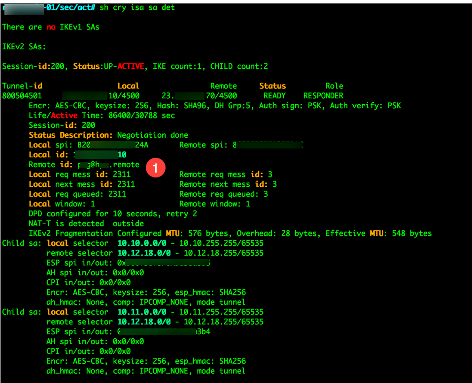
In the output, I have blured out some real information icluding the remote ID which is marked with the ‘1’.
You are also going to have to define the access-list normally assigned to outside interface if you do not have the ‘sysopt’ enabled but you should not.
no sysopt connection permit-vpn
This will require that you define what you want to allow into or out of the ASA. You will also need a ‘no nat’ NAT statement
nat (inside,outside) source static remoet-local remoet-local destination static remote remote
Obviously you would want to have descriptive names for the site not ‘remote’ but you can use something like branch1-local and branch-1 remote respectively.
On the Fortigate, log into the GUI and go to ‘Monitor, IPSec Monitor’ or you can run the following command:
get vpn ipse tun sum
Hope this helps you out.
Recent posts
-

-

DNS is one of those technologies that quietly underpins... Full Story
-

BGP issues on FortiGate firewalls usually trace back to... Full Story
-

Every time your laptop talks to your router, a... Full Story
-

If you've spent any time configuring NAT on a... Full Story
-

If you have spent any time configuring firewall policies... Full Story
-

High availability on FortiGate is one of those features... Full Story
-

If you've configured SD-WAN on a FortiGate, you've almost... Full Story
-

FortiLink is the management protocol that turns a FortiSwitch... Full Story
-

FortiSwitches are pretty rock solid from Mean Time Between... Full Story
-

This is a quicky tip. Have you ever gone... Full Story
-

DNS is one of those quiet pieces of internet... Full Story
-

This article is an updated version of the previous... Full Story
-

You will add ns2 as a secondary (slave) BIND9... Full Story
-

In the process of deploying my lab, I needed... Full Story
-

RFC 8805, used to be known as Self-Correcting IP... Full Story
-

Years back, I wrote an article about certificate pinning. ... Full Story
-

FortiGates have the ability to send alerts to Microsoft... Full Story
-

In this post, I am going to walk through... Full Story
-

Troubleshooting VoIP on a FortiGate can feel like trying... Full Story
-

Prior to FortiOS 7.0, there were three commands to... Full Story
-

In this post, I am going to go over... Full Story
-

What we are going to do: We are going... Full Story
-

Choosing between FGCP (FortiGate Clustering Protocol) and FGSP (FortiGate... Full Story
-

Creating a VLAN on macOS (The "Pro" Move) A... Full Story
-

This blog post explores the logic behind how macOS... Full Story
-

Pretty Fly for a Wi-Fi Tell My Wi-Fi Love... Full Story
-

Part of my daily gig is creating BoMs (Bill-of-Materials)... Full Story
-

ICMP introduces several security risks, but careful filtering, rate... Full Story
-

The command diag debug application dhcps -1 enables full... Full Story
-

In the world of FortiOS, execute tac report is... Full Story
-

LLDP; What is it The Link Layer Discovery Protocol... Full Story
-

What it actually does When you run diagnose fdsm... Full Story
-

Monkey Bites are bite-sized, high-impact security insights designed for... Full Story
-

I have run macOS in macOS with Parallels but... Full Story
-

Don't be confused with my other FortiNAC posts where... Full Story
-

This is the third session in a multi-part article... Full Story
-

Today I was configuring key-based authentication on a FortiGate... Full Story
-

Netcat, often called the "Swiss Army knife" of networking,... Full Story
-

At its core, IEEE 802.1X is a network layer... Full Story
-

In case you did not see the previous FortiNAC... Full Story
-

This is our 5th session where we are going... Full Story
-

Now that we have Wireshark installed and somewhat configured,... Full Story
-

The Philosophy of Packet Analysis Troubleshooting isn't about looking... Full Story
-

Have you ever wanted to do some testing on... Full Story
-

Ask ten engineers to define "a network" and you... Full Story
-

1. Executive Summary Objective: This guide turns a FortiAuthenticator... Full Story