
If you've spent any time configuring user authentication on... Full Story
By Manny Fernandez
September 9, 2026
Configuring Forward Error Correction on FortiGate
Executive Summary
Objective
Configure Forward Error Correction (FEC) on a FortiGate IPsec overlay, in both its static (fixed-ratio) and adaptive (SLA-driven) forms, and scope it to the traffic that actually benefits from it.
Target audience
Network and security engineers running FortiGate SD-WAN overlays who need to protect real-time UDP traffic (VoIP, video conferencing, remote desktop) against packet loss on links where waiting for a TCP-style retransmit isn’t acceptable: satellite backhaul, congested broadband, LTE/5G failover, or any WAN path with a non-trivial loss rate.
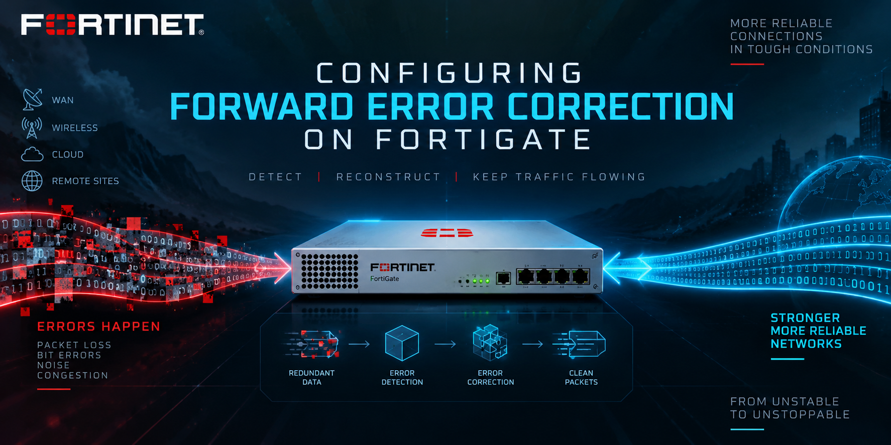
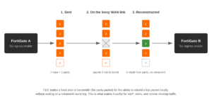
FEC works by sending redundant “parity” packets alongside the real traffic. If a packet is lost in transit, the receiving FortiGate rebuilds it locally from the parity data instead of waiting on the sender to notice and retransmit. That’s a fundamentally different failure mode than TCP retransmission: no round trip, no jitter spike, no dropped audio frame. The cost is bandwidth. Every parity packet you send is bandwidth you didn’t spend on real traffic, so the entire configuration exercise is really about tuning how much insurance you’re buying for how much packet loss you actually expect.
Prerequisites & Architecture
Assumed knowledge: Comfort with FortiGate CLI, IPsec phase1/phase2 configuration, and SD-WAN zones, members, and SLA health-checks. This guide assumes you already have a working IPsec overlay between two FortiGates, added as an SD-WAN member with a health-check monitoring it.
Environment and lab requirements
- FortiOS 6.2.0 or later for static (fixed base/redundant ratio) FEC.
- FortiOS 7.0.2 or later for adaptive FEC (mapping profiles,
fec-codec,fec-health-check), and for the current firewall-policy-scoped FEC model this guide uses. - Two FortiGates with an existing site-to-site IPsec tunnel, already configured as an SD-WAN zone member with a functioning performance SLA health-check.
- Lab addressing used throughout this guide:
198.18.0.0/15for public/transit addressing,10.0.0.0/16for internal LANs.
| Site | Role | WAN (transit) | Internal LAN |
|---|---|---|---|
| HQ-ATL | Hub, FortiGate A | 198.18.10.1 | 10.10.10.0/24 |
| Branch-DORAL | Spoke, FortiGate B | 198.18.20.1 | 10.20.10.0/24 |
| Tunnel interface | Overlay | 198.18.211.1 / .2 | n/a |
Component reference
| Component | Role |
|---|---|
config vpn ipsec phase1-interface |
Enables FEC per direction (fec-egress, fec-ingress) and sets the static base/redundant/timeout values |
config vpn ipsec fec |
Defines an adaptive mapping profile: a table of packet-loss, latency, and bandwidth thresholds, each mapped to its own base/redundant ratio |
fec-codec |
rs (Reed-Solomon, adaptive, responds to the mapping profile) or xor (fixed 1:1 parity, ignores mapping profile updates) |
fec-health-check |
Ties FEC’s adaptive behavior to the live metrics from an existing SD-WAN SLA health-check |
config firewall policy → set fec enable |
Scopes FEC to specific traffic. Mandatory since FortiOS 7.0.2; without it, FEC does nothing regardless of the phase1-interface settings |
npu-offload |
Hardware acceleration for the tunnel. FEC’s redundant packets are never NPU-offloaded, but everything else on the same tunnel still can be |
Step-by-Step Implementation Workflow
Step 1: Confirm the SD-WAN overlay and health-check are in place
Goal: FEC (especially the adaptive form) leans on an SD-WAN SLA health-check for its live packet-loss and latency numbers, so that has to exist first.
Action: This is a recap, not new config, assuming the overlay is already built:
config system sdwan
    set status enable
    config zone
        edit "virtual-wan-link"
        next
    end
    config members
        edit 1
            set interface "port1"
            set gateway 198.18.10.254
        next
        edit 2
            set interface "fec-tunnel"
        next
    end
    config health-check
        edit "fec-sla"
            set server "198.18.211.2"
            set members 2
            config sla
                edit 1
                next
            end
        next
    end
end
GUI verification: Network > SD-WAN > SD-WAN Zones, and Performance SLAs, should show the tunnel interface as a member with the health-check in an Up state.
Step 2: Enable static FEC on the phase1-interface
Goal: Get a baseline, fixed-ratio FEC working bidirectionally before layering in adaptive behavior. This is also the correct stopping point if you’re on FortiOS 6.2 through 7.0.1 and don’t need adaptive thresholds.
Action, on HQ-ATL:
config vpn ipsec phase1-interface
    edit "fec-tunnel"
        set fec-egress enable
        set fec-ingress enable
        set fec-base 20
        set fec-redundant 10
        set fec-send-timeout 8
        set fec-receive-timeout 5000
    next
end
Mirror the same block on Branch-DORAL. fec-base 20 / fec-redundant 10 means one parity packet for every two base packets, a 50% bandwidth overhead, which is heavy-handed for a first pass; it’s used here because it’s the FortiOS default. fec-send-timeout (default 8 ms) is how long the sender waits before flushing a parity packet; fec-receive-timeout (default 5000 ms) is how long the receiver holds a partial group waiting for the packet it needs to reconstruct.
GUI verification: As of current FortiOS releases, Fortinet’s own documentation only shows these phase1-interface FEC parameters configured via CLI. There’s no dedicated FEC section under VPN > IPsec Tunnels in the local FortiGate GUI (FortiManager exposes the same fields in its IPsec Tunnel Template editor, but that’s the management plane, not the device itself). Confirm the setting with show vpn ipsec phase1-interface fec-tunnel instead.
Step 3: Build an adaptive FEC mapping profile
Goal: Replace the flat, worst-case ratio from Step 2 with one that only spends bandwidth on parity when the link is actually degraded.
Action, on HQ-ATL:
config vpn ipsec fec
    edit "voip-mapping"
        config mappings
            edit 1
                set base 10
                set redundant 1
                set packet-loss-threshold 5
            next
            edit 2
                set base 8
                set redundant 2
                set packet-loss-threshold 10
            next
            edit 3
                set base 6
                set redundant 3
                set bandwidth-up-threshold 950000
            next
        end
    next
end
Rows are matched top to bottom, and the first row whose threshold is exceeded wins. Here: under 5% loss, send one parity packet per 10 base packets (roughly 10% overhead). Past 5% loss, tighten to 1-in-8 (12.5%). Past 10% loss, or if uplink bandwidth utilization crosses 950 Mbps, drop to 1-in-6 (about 17%). You can mix packet-loss, latency, and bandwidth thresholds in the same profile; a row is matched once any of its configured thresholds is exceeded.
Step 4: Attach the profile, codec, and health-check to the tunnel
Goal: Wire the mapping profile into the phase1-interface so FEC’s ratio actually moves in response to the health-check’s live metrics.
Action, on HQ-ATL (egress side):
config vpn ipsec phase1-interface
    edit "fec-tunnel"
        set npu-offload enable
        set fec-egress enable
        set fec-codec rs
        set fec-mapping-profile "voip-mapping"
        set fec-health-check "fec-sla"
        set fec-base 10
        set fec-redundant 1
    next
end
fec-codec rs (Reed-Solomon) is what makes the mapping profile matter: it’s the adaptive codec, and it’s the one that responds to the table you built in Step 3. The alternative, fec-codec xor, uses a fixed 1:1 parity scheme and ignores mapping profile updates entirely, so if you’ve built a mapping profile and FEC still isn’t adapting, check this setting first. fec-base 10 / fec-redundant 1 here is the fallback ratio in effect before any mapping profile threshold is exceeded; it should match your mapping profile’s first row.
Action, on Branch-DORAL (ingress side):
config vpn ipsec phase1-interface
    edit "fec-tunnel"
        set npu-offload enable
        set fec-ingress enable
    next
end
FEC is directional at the flag level: fec-egress generates and sends the parity stream, fec-ingress reconstructs from it. For two-way voice or video you’ll typically enable both flags on both ends, so each side is simultaneously sending its own parity stream and reconstructing the other side’s.
Step 5: Scope FEC to loss-sensitive traffic in the firewall policy
Goal: Since FortiOS 7.0.2, none of the above does anything until a matching set fec enable is also present on the firewall policy carrying the traffic. This is also your scoping mechanism: apply it only to the sessions that actually need it, since every session it touches gives up NPU offload for the duration.
Action, on Branch-DORAL:
config firewall policy
    edit 10
        set name "voip-fec"
        set srcintf "port10"
        set dstintf "virtual-wan-link"
        set srcaddr "branch-doral-lan"
        set dstaddr "all"
        set action accept
        set schedule "always"
        set service "ALL_UDP"
        set fec enable
        set nat enable
    next
    edit 11
        set name "general-no-fec"
        set srcintf "port10"
        set dstintf "virtual-wan-link"
        set srcaddr "branch-doral-lan"
        set dstaddr "all"
        set action accept
        set schedule "always"
        set service "ALL"
        set nat enable
    next
end
Policy 10 sits above policy 11, so UDP traffic hits the FEC-enabled rule first and everything else (bulk TCP transfers, for example, which already have their own retransmission logic and don’t benefit from FEC) falls through to the ordinary policy and keeps its NPU offload. This is the actual point of the two-rule split: narrowing which packets carry the FEC tax while the rest of the tunnel’s traffic stays fully accelerated.
GUI verification: Policy & Objects > Firewall Policy > edit the policy. A Forward Error Correction toggle appears in the policy’s advanced settings once the selected destination interface is a tunnel with FEC enabled on its phase1-interface. Menu wording has shifted slightly across FortiOS releases; if you don’t see it, show firewall policy 10 from the CLI will confirm the setting either way.
Verification & Validation
Run these on both FortiGates after configuration:
diagnose vpn tunnel list name fec-tunnelLook at the options field in the output. You’re looking for fec-egress and/or fec-ingress listed alongside the tunnel’s other flags, for example options[0e10]=create_dev frag-rfc fec-egress fec-ingress accept_traffic=1. If those flags aren’t present, the phase1-interface side of the config didn’t take; recheck Steps 2 and 4.
diagnose vpn ike gateway list name fec-tunnel
get vpn ipsec tunnel details
Confirm Phase 1 is up and that the enc (encrypted/sent) and dec (decrypted/received) packet counters are both climbing on both ends. If only one side’s counters are moving, you likely have an asymmetric egress/ingress configuration (see Gotcha 2 below).
diagnose sys sdwan health-check status fec-slaExpect a status of up, with packet-loss, latency, and jitter figures reported. While traffic is flowing, deliberately inducing loss on the link (a tc netem shim in a lab, or waiting for a naturally lossy window in production) should show the health-check’s packet-loss percentage rise, and the mapping profile’s more redundant row should take over as a result.
Finally, confirm the firewall policy itself is actually being matched:
get firewall policy 10Session and byte counters on policy 10 should climb as UDP traffic flows, while policy 11 carries everything else. Expected “success” state: FEC flags present in the tunnel options, matched enc/dec counters on both peers, the health-check reporting live metrics, and stable call or stream quality even when you intentionally introduce loss on the underlay.
Troubleshooting & Gotchas
FEC is configured on the tunnel but nothing is happening
This is almost always the firewall policy requirement from Step 5. FortiOS 7.0.2 changed FEC’s design so that phase1-interface settings alone are no longer sufficient; a matching set fec enable is also required on the policy carrying the traffic. If you upgraded from a pre-7.0.2 release with FEC already configured, this setting is not carried forward automatically and has to be added by hand; Fortinet’s release notes call this out explicitly as a breaking, non-backward-compatible change. Diagnostic path: confirm the tunnel options bitmask shows the fec flags (Verification section above), then check the policy with show firewall policy <id> for set fec enable.
Only one side’s counters are moving
FEC’s egress and ingress flags are a producer/consumer pair, not a single toggle. If Site A has fec-egress enable but Site B doesn’t have fec-ingress enable (or vice versa), Site A is generating and sending redundant packets that never get used for reconstruction on the other end, which burns bandwidth for zero benefit. Decide deliberately which direction(s) need protection; an asymmetric link like a satellite backhaul may only need one direction covered, while two-way voice needs both flags enabled on both peers.
The adaptive mapping profile never seems to change the ratio
Check fec-codec. xor is a fixed 1:1 parity codec and ignores mapping profile updates outright; it will not move off its configured base/redundant values no matter what the health-check reports. If adaptive behavior tied to a mapping profile is the goal, fec-codec has to be set to rs.
FEC is eating more bandwidth than the link can spare
FEC’s redundant packets are never NPU-offloaded, regardless of the npu-offload setting on the phase1-interface; only the non-FEC traffic on that tunnel benefits from hardware acceleration. If FEC is applied broadly (every service, every policy) rather than scoped narrowly to loss-sensitive UDP as in Step 5, you lose NPU offload for far more traffic than necessary and pay the parity-packet tax on traffic that didn’t need it. Narrow the scope first; if overhead is still too high for the link, raise fec-base (more base packets per redundant packet) to lower the ratio, accepting a lower reconstruction success rate under bursty loss in exchange for less overhead.
Recent posts
-

-

DNS is one of those technologies that quietly underpins... Full Story
-

BGP issues on FortiGate firewalls usually trace back to... Full Story
-

Every time your laptop talks to your router, a... Full Story
-

If you've spent any time configuring NAT on a... Full Story
-

If you have spent any time configuring firewall policies... Full Story
-

High availability on FortiGate is one of those features... Full Story
-

If you've configured SD-WAN on a FortiGate, you've almost... Full Story
-

FortiLink is the management protocol that turns a FortiSwitch... Full Story
-

FortiSwitches are pretty rock solid from Mean Time Between... Full Story
-

This is a quicky tip. Have you ever gone... Full Story
-

DNS is one of those quiet pieces of internet... Full Story
-

This article is an updated version of the previous... Full Story
-

You will add ns2 as a secondary (slave) BIND9... Full Story
-

In the process of deploying my lab, I needed... Full Story
-

RFC 8805, used to be known as Self-Correcting IP... Full Story
-

Years back, I wrote an article about certificate pinning. ... Full Story
-

FortiGates have the ability to send alerts to Microsoft... Full Story
-

In this post, I am going to walk through... Full Story
-

Troubleshooting VoIP on a FortiGate can feel like trying... Full Story
-

Prior to FortiOS 7.0, there were three commands to... Full Story
-

In this post, I am going to go over... Full Story
-

What we are going to do: We are going... Full Story
-

Choosing between FGCP (FortiGate Clustering Protocol) and FGSP (FortiGate... Full Story
-

Creating a VLAN on macOS (The "Pro" Move) A... Full Story
-

This blog post explores the logic behind how macOS... Full Story
-

Pretty Fly for a Wi-Fi Tell My Wi-Fi Love... Full Story
-

Part of my daily gig is creating BoMs (Bill-of-Materials)... Full Story
-

ICMP introduces several security risks, but careful filtering, rate... Full Story
-

The command diag debug application dhcps -1 enables full... Full Story
-

In the world of FortiOS, execute tac report is... Full Story
-

LLDP; What is it The Link Layer Discovery Protocol... Full Story
-

What it actually does When you run diagnose fdsm... Full Story
-

Monkey Bites are bite-sized, high-impact security insights designed for... Full Story
-

I have run macOS in macOS with Parallels but... Full Story
-

Don't be confused with my other FortiNAC posts where... Full Story
-

This is the third session in a multi-part article... Full Story
-

Today I was configuring key-based authentication on a FortiGate... Full Story
-

Netcat, often called the "Swiss Army knife" of networking,... Full Story
-

At its core, IEEE 802.1X is a network layer... Full Story
-

In case you did not see the previous FortiNAC... Full Story
-

This is our 5th session where we are going... Full Story
-

Now that we have Wireshark installed and somewhat configured,... Full Story
-

The Philosophy of Packet Analysis Troubleshooting isn't about looking... Full Story
-

InfoSecMonkey Threat Response October 24, 2026 | No fluff.... Full Story
-

InfoSecMonkey Threat Response October 24, 2026 | No fluff.... Full Story
-

Plus what you actually get with FortiCare Essential, Premium... Full Story