If you've spent any time configuring user authentication on... Full Story
By Manny Fernandez
May 14, 2026
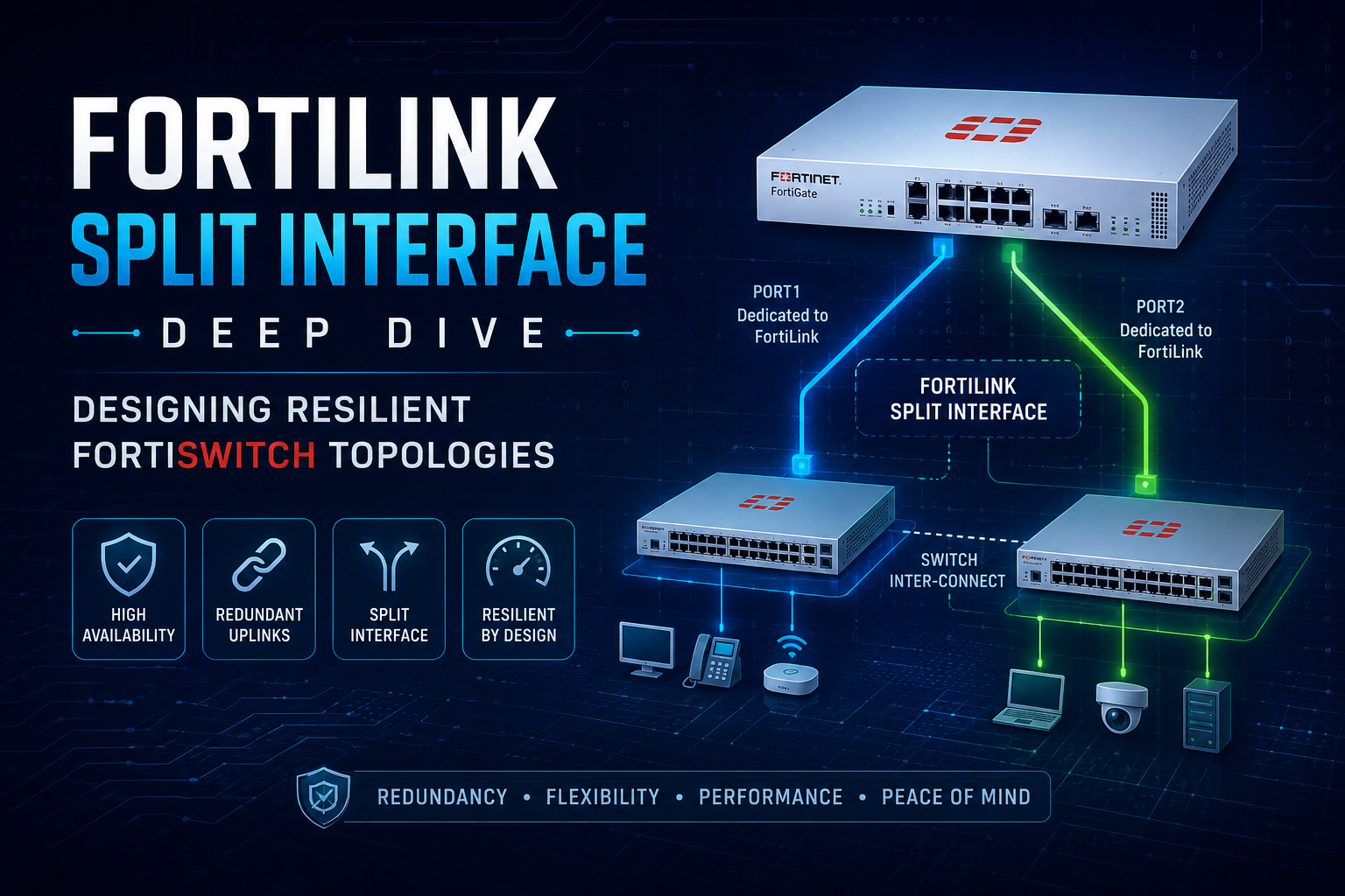
FortiLink Split Interface Deep Dive: Designing Resilient FortiSwitch Topologies
FortiLink is the management protocol that turns a FortiSwitch into an extension of the FortiGate’s switching fabric. Once a FortiSwitch is managed over FortiLink, the FortiGate owns its configuration, VLANs, port state, and policy. That’s powerful, but it also means the FortiLink connection itself becomes a single point of failure unless you design around it. In this article I will cover three major deployments; A. Two FortiGates and One Switch. B. Two FortiGates and Two FortiSwitches and Finally, C. One FortiGate. and One Switch with multiple connection.
The FortiLink split interface feature exists precisely to solve part of that problem. It is one of the most misunderstood features in the FortiSwitch management stack, largely because the term “split interface” gets conflated with “redundancy,” and because the correct design depends heavily on whether you have one FortiGate or two, and one FortiSwitch or two.
This post walks through four topologies, explains exactly when the split interface is required, when it is forbidden, and what the inter-switch link (ISL) does in the two-switch designs. I’ll also call out the gotchas that generate the most TAC tickets.
Terms
First, Some Terms we use in this article
Before the topologies, let’s pin down terms, because sloppy terminology is the root of most FortiLink confusion.
FortiLink interface – A logical interface on the FortiGate (commonly named fortilink) that is designated as the management channel for FortiSwitches. It is built on top of a hardware or software interface, and most importantly it is almost always a LAG (link aggregation group / 802.3ad trunk) so that multiple physical ports can carry FortiLink.
FortiLink split interface – A specific mode of the FortiLink LAG. When the split interface is enabled, the LAG is allowed to have its member ports connect to two different FortiSwitches, but only one member is active at a time. It is effectively an active/standby arrangement across two switches. When the split interface is disabled, the LAG behaves as a normal aggregated bundle and all members are expected to terminate on the same switch (or same logical switch, i.e., a stack/tier).

MCLAG (Multi-Chassis LAG) — A pair of FortiSwitches presenting themselves as a single logical LAG peer to an upstream or downstream device. MCLAG is the active/active alternative to the split interface, and it requires an ICL (Inter-Chassis Link) between the two switches.
ISL / ICL – The link(s) between two FortiSwitches. In a generic Layer 2 sense it’s an inter-switch link (ISL). When that link is specifically the peer link for an MCLAG pair, Fortinet calls it the ICL (Inter-Chassis Link). The distinction matters and we’ll return to it.
FortiGate HA – Two FortiGates in a high-availability cluster (A-P or A-A). From the FortiSwitch’s perspective, an HA cluster is one logical FortiGate; only the primary unit actively manages the switches, and management state synchronizes to the secondary.
The single most important conceptual point: the split interface is a property of the FortiLink LAG on the FortiGate side, and it governs how that LAG is allowed to fan out to switches. It is not a switch-side redundancy protocol. MCLAG is the switch-side story.
Topology A – Two FortiGates, One FortiSwitch
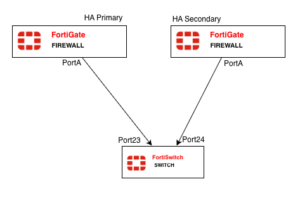
Two FortiGates in an HA cluster, each running one (or more) FortiLink cable down to the same single FortiSwitch.
Is the split interface used here?
Yes – and this is the canonical use case for it. This is the textbook reason the split interface feature exists.
Here’s the problem it solves. Your two FortiGates are an HA pair, so they share one configuration and one FortiLink LAG definition. That LAG has a member going to the switch from FortiGate-A and a member going to the switch from FortiGate-B. If the LAG tried to aggregate both of those links normally, you’d have a broken LACP bundle, the two physical links terminate on two different chassis on the FortiGate side, and the single FortiSwitch would see what looks like one LAG peer trying to bundle ports that aren’t actually a coherent aggregation. Loops, flapping, and a switch that won’t come under management.
Enabling the FortiLink split interface tells the FortiGate: this LAG spans two chassis; keep only one member link active at a time. The link from the HA primary is active; the link from the HA secondary is standby. On failover, the previously-standby link becomes active. The FortiSwitch only ever talks to one FortiGate at a time, which is exactly what you want, because only the HA primary should be managing it anyway.
On the FortiGate (HA cluster, configured once):
config system interface
edit "fortilink"
set fortilink enable
set member "port1"# link toward the switch from this slot
set lacp-mode static# in an HA pair, the equivalent port on the secondary is implicitly part of the picture
next
end
In practice, on modern FortiOS you set it directly on the FortiLink interface:
config system interface
edit "fortilink"
set fortilink-split-interface enable
next
endWhen the split interface is enabled and you look at the interface, you’ll see the member ports listed but only one forwarding.
When to use Topology A
Use this when you have a FortiGate HA pair but only need to manage a single switch (small branch, compact wiring closet) and you want switch management to survive a FortiGate failover. It is the *minimum* resilient design for an HA FortiGate deployment.
Gotchas
– The split interface must be enabled, or HA + single switch will not work cleanly. This is the number one mistake: people build a FortiGate HA pair, cable both units to one switch, leave the FortiLink LAG in normal mode, and then chase phantom loop/flap problems. If two FortiGates touch one switch, the split interface is mandatory.
– You lose aggregated bandwidth on the FortiLink path. Because only one member is active, you do not get 2× throughput on the management/data path between the active FortiGate and the switch. If you need both redundancy *and* aggregated bandwidth from a single FortiGate, you must run *multiple* links from the *same* FortiGate into the switch as a normal LAG, *in addition to* the split arrangement across chassis — which gets complex fast. Most designs accept the single-active-link tradeoff.
– Don’t confuse this with MCLAG. There is only one switch here; MCLAG is irrelevant. The split interface is the entire redundancy story for Topology A.
– LACP mode. With the split interface, the LAG is not a “real” bundle in the LACP sense. Keep the FortiLink LAG mode consistent with Fortinet’s defaults for FortiLink (FortiLink typically uses a static/fortilink-managed aggregation rather than a fully negotiated 802.3ad bundle). Don’t hand-tune LACP timers here expecting normal LAG behavior.
Topology B — Two FortiGates, Two FortiSwitches
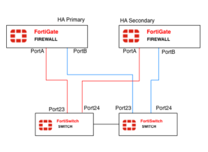
Two FortiGates in HA, two FortiSwitches, and the switches connected to each other by an inter-switch link. Each FortiGate has links down to both switches.
Is the split interface used here?
Yes, the split interface is still enabled, for the same reason as Topology A: two FortiGate chassis are participating in the FortiLink LAG, so the LAG must be in split mode so that only the HA primary’s links are active.
But now there’s a second dimension: you have two switches, and you have to decide how those two switches relate to each other. This is where the inter-switch link and the choice between a plain ISL and an MCLAG ICL comes in.
The inter-switch connection: two ways to do it
Option B1-Tiered / standalone switches with a normal ISL.
The two FortiSwitches are independent. The link between them is an ordinary Layer 2 trunk. Spanning tree (FortiSwitches run RSTP/MSTP) keeps the topology loop-free. Each switch is its own FortiLink peer to the FortiGate. This is simple and works, but:
– STP will block one of the redundant paths, so you don’t get full path utilization.
– Convergence on a failure is STP-speed, not sub-second.
– Downstream devices that are dual-homed to both switches cannot form a single LAG across them, they’d need their own STP or active/standby.
Option B2 — MCLAG pair with an ICL.
The two FortiSwitches are configured as an MCLAG peer pair (Only available on 200Series and above). The link between them is promoted to an ICL (Inter-Chassis Link), typically itself a multi-port LAG for resilience. Now the two switches present a single logical LAG identity both upward (to the FortiGate) and downward (to dual-homed servers, APs, or access switches).
Benefits:
– Active/active forwarding — no STP-blocked links between the pair.
– Sub-second failover if one switch dies.
– Downstream devices can run a normal LACP LAG split across both switches and just see “one switch.”
For Topology B in any serious deployment, B2 (MCLAG with ICL) is the recommended inter-switch connection. The plain ISL (B1) is acceptable only for low-stakes environments or where the FortiSwitch models don’t support MCLAG.
How the split interface and MCLAG coexist
This is the part that trips people up. In Topology B you have two redundancy mechanisms operating on two different axes, and they are complementary, not alternatives:
– FortiGate-side redundancy is handled by FortiGate HA + the FortiLink split interface. The split interface ensures only the primary FortiGate’s links are active.
– Switch-side redundancy is handled by MCLAG + the ICL. MCLAG ensures that if one switch fails, the other keeps forwarding, and that dual-homed endpoints stay up.
You enable the split interface on the FortiLink LAG and you configure the two switches as an MCLAG pair with an ICL. They don’t conflict, they cover different failure domains.
FortiGate side (HA cluster) — split interface on, FortiLink LAG has members toward both switches:
config system interface
edit "fortilink"
set fortilink enable
set fortilink-split-interface enable
set member "port1" "port2"# e.g. port1 -> FSW-1, port2 -> FSW-2
next
end
FortiSwitch MCLAG side, configure the ICL trunk and mark it as the MCLAG peer link. On FortiOS-managed switches this is done from the FortiGate via the managed-switch context:
config switch-controller managed-switch
edit "FSW-1-serial"
config ports
edit "ICL-trunk"
set type trunk
set mclag-icl enable
set members "port47" "port48"
next
end
next
edit "FSW-2-serial"
config ports
edit "ICL-trunk"
set type trunk
set mclag-icl enable
set members "port47" "port48"
next
end
next
end
Then any downstream LAG you want dual-homed across the pair is created as an MCLAG trunk (set mclag enable on the trunk on both switches with matching configuration).
When to use Topology B
This is the full high-availability reference design and is what you should propose for any environment where both the firewall and the access layer need to survive a single hardware failure: data center top-of-rack, core campus wiring closets, anything carrying production traffic with an SLA. If the customer bought FortiGate HA, they almost certainly should also be running two switches in MCLAG, otherwise the access layer is the weak link in an otherwise-redundant design.
Gotchas
– ICL must be a LAG, and it must be sized. Putting the ICL on a single port is a design smell. The ICL carries synchronization traffic and, during certain failure conditions, actual user traffic that has to hairpin between switches. Use at least two ports, and on busy pairs use higher-speed ports. An undersized ICL becomes a congestion point that only shows up under failure, the worst time to discover it.
– MCLAG requires matching FortiSwitch models / firmware. You cannot reliably MCLAG two dissimilar switch models. Keep the pair identical, and keep their FortiOS/FortiSwitch firmware in lockstep, the FortiGate manages this, but version skew during upgrades can break the pair temporarily.
– The split interface is still required, don’t drop it because “MCLAG handles redundancy.” MCLAG handles switch redundancy. It does nothing about the fact that two FortiGate chassis are on the FortiLink LAG. Disable the split interface and you reintroduce the two-chassis LAG problem from Topology A. Both features on, always, in this topology.
– MCLAG peer-link / keepalive consistency. The two switches must agree on MCLAG configuration. Mismatched VLANs across the ICL, or an ICL that isn’t trunking all the right VLANs, leads to traffic that works for some VLANs and blackholes for others, a miserable thing to troubleshoot.
– STP still runs. Even with MCLAG, spanning tree is active as a backstop. Make sure the FortiGate/FortiSwitch STP root placement is deliberate (root should be the MCLAG pair, not some random access switch downstream). An accidental STP root election on a downstream device can wreck convergence.
– FortiLink heartbeat VLAN. FortiLink uses a dedicated heartbeat/management VLAN. In a two-switch design make sure that VLAN is carried correctly across the ICL, or a switch can end up “managed” but isolated.
Topology C — One FortiGate, One FortiSwitch
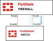
The simplest possible managed-switch deployment. One FortiGate, one FortiSwitch, one (or more) cables between them.
Is the split interface used here?
No.
The split interface must be DISABLED in this topology. This is the second-most-common mistake after forgetting to enable it in HA designs, people enable the split interface reflexively because they read that it’s “for redundancy.”
There is only one FortiGate chassis. There is no two-chassis LAG problem to solve. If you enable the split interface here, you are telling the FortiGate to keep only one LAG member active, which means if you cabled two links between the single FortiGate and the single switch hoping for an aggregated, redundant bundle, you just disabled half of it. One link sits idle in standby for no reason.
What you actually want here
With one FortiGate and one switch, if you want both redundancy and bandwidth on the FortiLink path, you run multiple physical links between them as a normal LAG, split interface disabled. All members are active, you get aggregated throughput, and if one cable fails the LAG simply continues on the remaining members. That is ordinary link aggregation doing its job, and it’s the correct tool because both ends of the LAG terminate on a single chassis.
Recent posts
-

-

DNS is one of those technologies that quietly underpins... Full Story
-

BGP issues on FortiGate firewalls usually trace back to... Full Story
-

Every time your laptop talks to your router, a... Full Story
-

If you've spent any time configuring NAT on a... Full Story
-

If you have spent any time configuring firewall policies... Full Story
-

High availability on FortiGate is one of those features... Full Story
-

If you've configured SD-WAN on a FortiGate, you've almost... Full Story
-

FortiLink is the management protocol that turns a FortiSwitch... Full Story
-

FortiSwitches are pretty rock solid from Mean Time Between... Full Story
-

This is a quicky tip. Have you ever gone... Full Story
-

DNS is one of those quiet pieces of internet... Full Story
-

This article is an updated version of the previous... Full Story
-

You will add ns2 as a secondary (slave) BIND9... Full Story
-

In the process of deploying my lab, I needed... Full Story
-

RFC 8805, used to be known as Self-Correcting IP... Full Story
-

Years back, I wrote an article about certificate pinning. ... Full Story
-

FortiGates have the ability to send alerts to Microsoft... Full Story
-

In this post, I am going to walk through... Full Story
-

Troubleshooting VoIP on a FortiGate can feel like trying... Full Story
-

Prior to FortiOS 7.0, there were three commands to... Full Story
-

In this post, I am going to go over... Full Story
-

What we are going to do: We are going... Full Story
-

Choosing between FGCP (FortiGate Clustering Protocol) and FGSP (FortiGate... Full Story
-

Creating a VLAN on macOS (The "Pro" Move) A... Full Story
-

This blog post explores the logic behind how macOS... Full Story
-

Pretty Fly for a Wi-Fi Tell My Wi-Fi Love... Full Story
-

Part of my daily gig is creating BoMs (Bill-of-Materials)... Full Story
-

ICMP introduces several security risks, but careful filtering, rate... Full Story
-

The command diag debug application dhcps -1 enables full... Full Story
-

In the world of FortiOS, execute tac report is... Full Story
-

LLDP; What is it The Link Layer Discovery Protocol... Full Story
-

What it actually does When you run diagnose fdsm... Full Story
-

Monkey Bites are bite-sized, high-impact security insights designed for... Full Story
-

I have run macOS in macOS with Parallels but... Full Story
-

Don't be confused with my other FortiNAC posts where... Full Story
-

This is the third session in a multi-part article... Full Story
-

Today I was configuring key-based authentication on a FortiGate... Full Story
-

Netcat, often called the "Swiss Army knife" of networking,... Full Story
-

At its core, IEEE 802.1X is a network layer... Full Story
-

In case you did not see the previous FortiNAC... Full Story
-

This is our 5th session where we are going... Full Story
-

Now that we have Wireshark installed and somewhat configured,... Full Story
-

The Philosophy of Packet Analysis Troubleshooting isn't about looking... Full Story
-

What MIMO Actually Does Multiple Input, Multiple Output (MIMO)... Full Story
-

Let me start by saying, if you do not... Full Story
-

At work, they wanted us to keep track of... Full Story