
If you've spent any time configuring user authentication on... Full Story
By Manny Fernandez
July 27, 2026
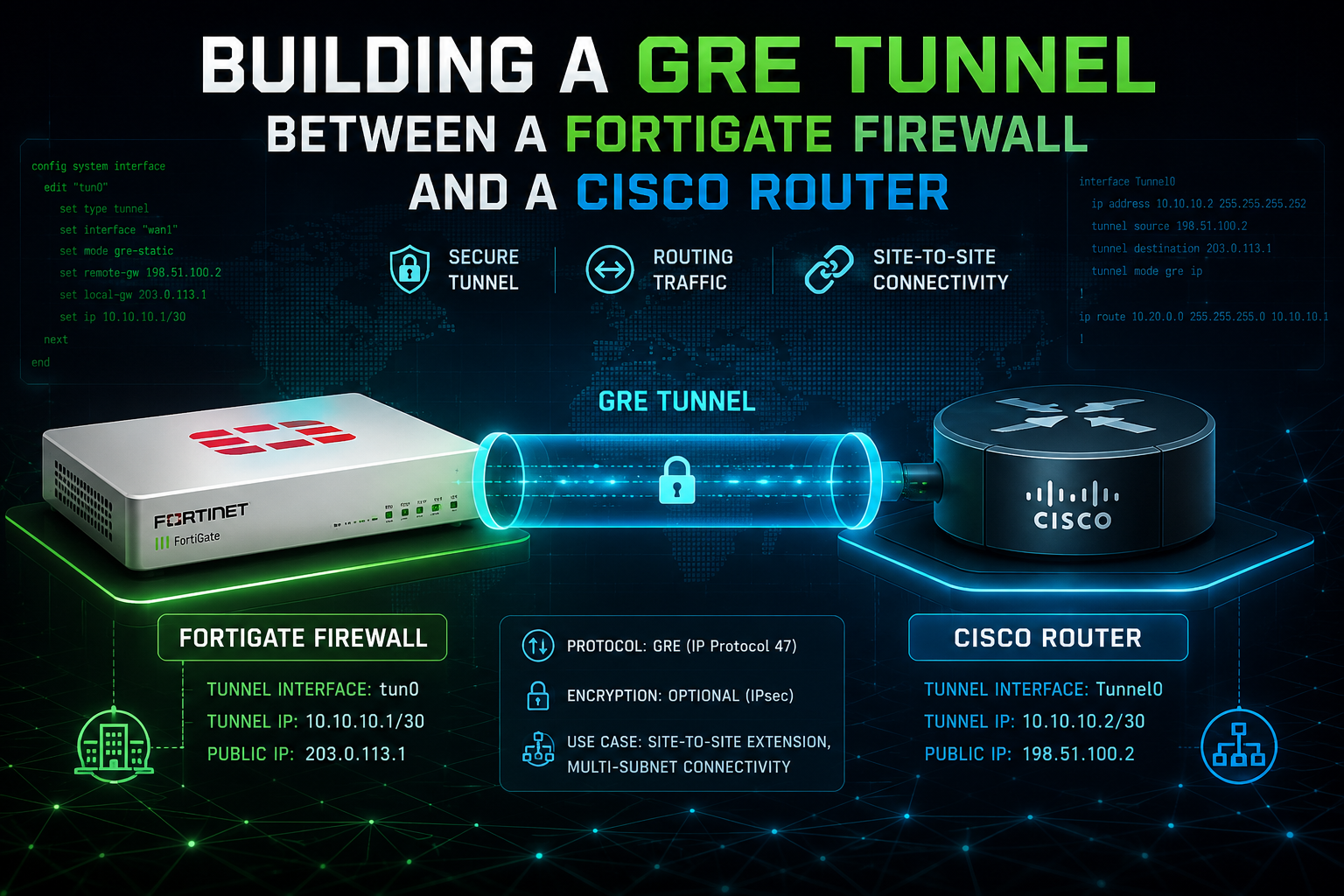
Building a GRE Tunnel Between a FortiGate Firewall and a Cisco Router
1. Executive Summary
Objective
This guide walks through the end-to-end deployment of a Generic Routing Encapsulation (GRE) tunnel between a FortiGate running FortiOS 7.x and a Cisco 2900 Series Integrated Services Router (ISR G2) running IOS 15.x. GRE gives you a routable, multiprotocol point-to-point link across an untrusted or third-party transit network, which is exactly what you need when a partner network, a legacy WAN circuit, or a carrier hand-off cannot terminate IPsec, or when you need a transport that routing protocols and multicast can traverse. By the end, you will have a tunnel interface pair carrying routed traffic between two LAN segments, with correct MTU handling, liveness detection, and firewall policy in place.
Target Audience
Network Engineers, Security Engineers, and Systems Administrators responsible for hybrid Fortinet and Cisco environments. This is written for practitioners who will be typing these commands into production gear, not for a conceptual overview audience.
Important: GRE provides encapsulation, not encryption. Every byte inside the tunnel crosses the transit network in cleartext. If the transit path is anything other than a private, trusted circuit, protect the GRE tunnel inside IPsec or use a native IPsec tunnel instead. The IPsec-protected variant is covered in the Gotchas section.
2. Prerequisites & Architecture
Assumed Knowledge
You should already be comfortable with the following before starting:
- IPv4 addressing, subnetting, and static routing fundamentals
- FortiOS CLI structure (
config/edit/set/next/end) and the FortiGate GUI layout - Cisco IOS configuration modes, interface configuration, and
showcommand syntax - Basic firewall policy construction on FortiGate, including source and destination interface matching
- Reading packet captures at a basic level (protocol numbers, encapsulation layers)
Environment and Lab Requirements
| Requirement | Detail |
|---|---|
| FortiGate hardware or VM | Any model running FortiOS 6.4 or later. Examples validated on FortiOS 7.4.x. |
| FortiGate licensing | None required. GRE is a base FortiOS feature and does not consume a UTM or security subscription. |
| Cisco router | Cisco 2901, 2911, 2921, or 2951 (ISR G2) running IOS 15.1(4)M or later. Examples validated on 15.7(3)M. |
| Cisco licensing | ipbasek9 is sufficient for plain GRE. securityk9 is required only if you later wrap the tunnel in IPsec. |
| Transit path | IP reachability between the two public or transit-facing interfaces, with IP protocol 47 permitted end to end. |
| Administrative access | Super-admin on the FortiGate, privilege level 15 on the router, plus out-of-band console access on both. |
| Lab option | Both platforms virtualize cleanly. FortiGate-VM plus Cisco IOSv or CSR1000v in EVE-NG or GNS3 reproduces this topology, though IOSv does not model 2900-series hardware queueing behavior. |
Reference Topology
The transit network is treated as an opaque L3 cloud. Neither device needs to know anything about the path between them beyond a default route.
   10.0.10.0/24                                                  10.0.20.0/24
   HQ LAN                                                        Branch LAN
      |                                                               |
   [port5]                                                        [Gi0/1]
  +-----------------+                                        +------------------+
  |    FortiGate    |                                        |   Cisco 2911     |
  |    FortiOS 7.4  |                                        |   IOS 15.7(3)M   |
  +-----------------+                                        +------------------+
   [wan1]                                                         [Gi0/0]
   198.18.1.10/29                                                 198.18.2.20/29
      |                                                               |
      +-------------------[ Transit / Internet ]----------------------+
                                     |
                       GRE tunnel: 172.16.31.0/30
                       FortiGate gre-to-c2911 = 172.16.31.1
                       Cisco Tunnel0          = 172.16.31.2
Component Table
| Component | Role | Interface | IP / FQDN | Notes |
|---|---|---|---|---|
| FortiGate 100F | Tunnel endpoint, HQ edge firewall | wan1 | 198.18.1.10/29 | GRE local gateway |
| FortiGate 100F | HQ LAN gateway | port5 | 10.0.10.1/24 | Protected subnet 10.0.10.0/24 |
| FortiGate 100F | GRE tunnel interface | gre-to-c2911 | 172.16.31.1/30 | Logical interface, bound to wan1 |
| Cisco 2911 | Tunnel endpoint, branch edge router | Gi0/0 | 198.18.2.20/29 | GRE tunnel source |
| Cisco 2911 | Branch LAN gateway | Gi0/1 | 10.0.20.1/24 | Protected subnet 10.0.20.0/24 |
| Cisco 2911 | GRE tunnel interface | Tunnel0 | 172.16.31.2/30 | Logical interface |
| Transit network | Underlay transport | n/a | n/a | Must permit IP protocol 47 bidirectionally |
Addresses used throughout are non-routable lab ranges. The 198.18.0.0/15 block (RFC 2544 benchmarking) stands in for the public or transit-facing addresses, and 10.0.0.0/16 (RFC 1918) covers the internal LANs, so nothing in this guide will collide with live production space if a snippet is pasted by mistake. Substitute your own values wherever you see a placeholder in angle brackets, for example <fortigate_wan_ip>.
3. Step-by-Step Implementation Workflow
Phase 1: Underlay Validation and Pre-Flight
The Goal: Prove that the two tunnel endpoints can reach each other over the transit network before introducing any tunnel configuration. Roughly half of all “GRE tunnel will not come up” tickets are underlay reachability or protocol-47 filtering problems that were never validated first.
The Action: From each device, source a ping from the interface that will become the tunnel source, targeting the far-end tunnel destination. Sourcing matters: a ping that succeeds from the default source address but fails from the tunnel source address indicates an asymmetric routing or NAT problem that will break GRE.
FortiGate CLI:
execute ping-options reset
execute ping-options source <fortigate_wan_ip>
execute ping <cisco_wan_ip>

# Confirm the route the FortiGate will actually use toward the peer
get router info routing-table details <cisco_wan_ip>
Cisco IOS CLI:
ping <fortigate_wan_ip> source GigabitEthernet0/0

! Confirm the route toward the peer
show ip route <fortigate_wan_ip>
show ip cef <fortigate_wan_ip>
GUI Verification (FortiGate): Navigate to Network > Diagnostics > Ping (available on FortiOS 7.2 and later) to run the sourced ping from the GUI, or confirm the egress interface under Network > Static Routes.
Gotcha: If either endpoint sits behind a NAT device, stop here and read the NAT discussion in Section 5. GRE has no port numbers, so PAT will silently break the tunnel and no amount of tunnel configuration will fix it.
Phase 2: Configure the Cisco 2911 Tunnel Interface
The Goal: Create the Tunnel0 interface, bind it to the physical WAN interface, and point it at the FortiGate.
The Action: Build the tunnel interface with an explicit tunnel mode gre ip. Although GRE over IPv4 is the IOS default, stating it explicitly makes the intent obvious to the next engineer and protects you from an inherited template that changed the mode. Set ip mtu and ip tcp adjust-mss at creation time rather than adding them after the first fragmentation complaint.
Cisco IOS CLI:
configure terminal
!
interface Tunnel0
 description GRE to FortiGate HQ
 ip address 172.16.31.2 255.255.255.252
 ip mtu 1476
 ip tcp adjust-mss 1436
 tunnel source GigabitEthernet0/0
 tunnel destination <fortigate_wan_ip>
 tunnel mode gre ip
 no shutdown
!
end
write memory
Key parameter notes:
tunnel sourceshould reference the interface, not the IP address, so the tunnel survives a re-addressing of the WAN interface. If the router has multiple egress paths, reference a Loopback only when both sides can route to that Loopback.ip mtu 1476accounts for the 24-byte GRE overhead (20-byte outer IPv4 header plus 4-byte GRE header) against a 1500-byte underlay MTU.ip tcp adjust-mss 1436clamps the TCP MSS to 1476 minus 40 bytes of TCP/IP header. This only helps TCP; UDP and ICMP still depend on correct MTU and PMTUD behavior.
Phase 3: Create the GRE Tunnel Object on the FortiGate
The Goal: Define the GRE encapsulation itself. On FortiOS this is a two-part operation: the system gre-tunnel object defines the encapsulation, and a separate system interface edit assigns the tunnel IP addressing. Missing the second half is the single most common FortiGate-side error.
The Action: Create the tunnel object bound to the physical WAN interface, specifying both the local and remote gateway addresses. Naming the object something operationally meaningful pays off later, because this name becomes the interface name used in routes, policies, and logs.
FortiGate CLI:
config system gre-tunnel
    edit "gre-to-c2911"
        set interface "wan1"
        set local-gw <fortigate_wan_ip>
        set remote-gw <cisco_wan_ip>
        set dscp-copying enable
    next
end
Optional parameters worth knowing:
| Parameter | Purpose | Interop note |
|---|---|---|
set key-outbound / set key-inbound |
GRE key field, matching the Cisco tunnel key value |
Both sides must match exactly, or all packets are dropped silently |
set checksum-transmission / set checksum-reception |
Enables the GRE checksum field | Leave disabled unless the far end requires it; adds per-packet cost |
set sequence-number-transmission |
Adds GRE sequence numbers | Rarely needed; Cisco requires tunnel sequence-datagrams to match |
set dscp-copying enable |
Copies inner DSCP to the outer header | Required if the transit provider honors DSCP for QoS |
set auto-asic-offload |
Controls NPU offload of GRE sessions | Leave enabled in production; disable temporarily when troubleshooting |
GUI Verification: Navigate to Network > Interfaces. The GRE tunnel appears nested beneath its parent physical interface (wan1) once both the tunnel object and the interface addressing exist.
Phase 4: Assign Tunnel Interface Addressing on the FortiGate
The Goal: Give the FortiGate side of the tunnel a routable IP so that static routes and routing protocols can use it as a next hop.
The Action: Edit the interface object that FortiOS auto-created when you defined the GRE tunnel. Use the set ip plus set remote-ip pattern that FortiOS uses for all point-to-point tunnel interfaces. Enable ping on allowaccess for the duration of the deployment so that you can validate the tunnel independently of user traffic.
FortiGate CLI:
config system interface
    edit "gre-to-c2911"
        set ip 172.16.31.1 255.255.255.255
        set remote-ip 172.16.31.2 255.255.255.252
        set allowaccess ping
        set mtu-override enable
        set mtu 1476
    next
end
Notes on this block:
set ipwith a255.255.255.255mask plusset remote-ipcarrying the real subnet mask is the canonical FortiOS tunnel-interface pattern. Some builds also accept the full mask onset ip; the canonical form is portable across versions.set mtu-override enableis required beforeset mtuwill be accepted. If your build does not exposemtu-overrideon a GRE interface, rely on TCP MSS clamping in policy (Phase 6) instead.- Remove
set allowaccess pingafter the deployment is validated if your security standard forbids management protocols on tunnel interfaces.
GUI Verification: Navigate to Network > Interfaces, expand wan1, and confirm gre-to-c2911 shows the correct IP and remote IP. The interface status indicator will be green once the tunnel object is complete, though on GRE a green indicator only means the interface is administratively up, not that the far end is responding.
Phase 5: Routing Across the Tunnel
The Goal: Steer the traffic destined for the remote LAN into the tunnel interface on both devices.
The Action: Start with static routes. They are deterministic, they make the first round of troubleshooting far simpler, and they can be replaced with a dynamic protocol once the data plane is proven. An OSPF variant is included below for environments that require it.
FortiGate CLI (static):
config router static
    edit 0
        set dst 10.0.20.0 255.255.255.0
        set device "gre-to-c2911"
        set comment "Branch LAN via GRE"
    next
end
On a point-to-point tunnel interface the set gateway line is optional; FortiOS will use the interface as the next hop. Include set gateway 172.16.31.2 if your operational standard requires an explicit next hop.
Cisco IOS CLI (static):
configure terminal
ip route 10.0.10.0 255.255.255.0 172.16.31.1 name HQ-LAN-via-GRE
end
write memory
Always specify the next-hop IP rather than the interface alone. ip route 10.0.10.0 255.255.255.0 Tunnel0 works on a point-to-point tunnel but generates unnecessary ARP-equivalent resolution behavior and makes the recursive routing failure mode harder to diagnose.
Optional: OSPF over the tunnel. If you need dynamic routing, run it across the tunnel interface only, never across the transit interfaces.
Cisco IOS CLI (OSPF):
configure terminal
!
interface Tunnel0
 ip ospf network point-to-point
 ip ospf mtu-ignore
!
router ospf 10
 network 172.16.31.0 0.0.0.3 area 0
 network 10.0.20.0 0.0.0.255 area 0
 passive-interface GigabitEthernet0/1
!
end
FortiGate CLI (OSPF):
config router ospf
    set router-id 10.0.10.1
    config area
        edit 0.0.0.0
        next
    end
    config ospf-interface
        edit "gre-ospf"
            set interface "gre-to-c2911"
            set network-type point-to-point
            set mtu-ignore enable
        next
    end
    config network
        edit 1
            set prefix 172.16.31.0 255.255.255.252
            set area 0.0.0.0
        next
        edit 2
            set prefix 10.0.10.0 255.255.255.0
            set area 0.0.0.0
        next
    end
end
Gotcha:
mtu-ignoreon both sides is not cosmetic. FortiGate and IOS calculate and advertise tunnel interface MTU differently, and the resulting mismatch parks the adjacency in EXSTART or EXCHANGE indefinitely. See Section 5.
Phase 6: Firewall Policy and Local-In Policy
The Goal: Permit user traffic to traverse the tunnel, and make sure the FortiGate itself accepts the inbound GRE packets.
The Action: GRE tunnel interfaces are ordinary interfaces from the policy engine’s point of view. Traffic entering or leaving the tunnel requires an explicit firewall policy in each direction. Do not enable NAT on these policies unless you have a deliberate overlapping-subnet requirement.
FortiGate CLI:
config firewall address
    edit "HQ-LAN-10.0.10.0"
        set subnet 10.0.10.0 255.255.255.0
    next
    edit "BRANCH-LAN-10.0.20.0"
        set subnet 10.0.20.0 255.255.255.0
    next
end

config firewall policy
    edit 0
        set name "HQ-to-Branch-GRE"
        set srcintf "port5"
        set dstintf "gre-to-c2911"
        set srcaddr "HQ-LAN-10.0.10.0"
        set dstaddr "BRANCH-LAN-10.0.20.0"
        set action accept
        set schedule "always"
        set service "ALL"
        set logtraffic all
        set tcp-mss-sender 1436
        set tcp-mss-receiver 1436
    next
    edit 0
        set name "Branch-to-HQ-GRE"
        set srcintf "gre-to-c2911"
        set dstintf "port5"
        set srcaddr "BRANCH-LAN-10.0.20.0"
        set dstaddr "HQ-LAN-10.0.10.0"
        set action accept
        set schedule "always"
        set service "ALL"
        set logtraffic all
        set tcp-mss-sender 1436
        set tcp-mss-receiver 1436
    next
end
Setting service ALL is a bring-up convenience. Tighten it to the actual application set before the change window closes.
Local-in policy consideration: By default, a FortiGate with a configured GRE tunnel object accepts protocol 47 destined to the configured local-gw. If your build enforces a restrictive local-in policy set, or if the WAN interface sits behind an upstream ACL, you must explicitly permit GRE:
config firewall local-in-policy
    edit 0
        set intf "wan1"
        set srcaddr "CISCO-2911-PEER"
        set dstaddr "FGT-WAN-IP"
        set service "GRE"
        set schedule "always"
        set action accept
    next
end
GRE is a predefined FortiOS service object mapping to IP protocol 47.
Cisco ACL consideration: If Gi0/0 carries an inbound ACL, protocol 47 must be permitted from the FortiGate peer:
configure terminal
ip access-list extended OUTSIDE-IN
 permit gre host <fortigate_wan_ip> host <cisco_wan_ip>
end
GUI Verification: Navigate to Policy & Objects > Firewall Policy and confirm both policies exist, that gre-to-c2911 appears as an interface option, and that the NAT toggle is off.
Phase 7: Liveness Detection
The Goal: Ensure the tunnel interface reflects the true reachability of the far end so that routing withdraws correctly on failure. Without liveness detection, a GRE tunnel interface stays administratively up forever, black-holing traffic even when the peer is gone.
The Action: Choose exactly one mechanism and use it consistently. The three viable options are GRE keepalives, a routing protocol adjacency, or a FortiGate link monitor.
Option A, GRE keepalives. Cisco originated the mechanism, and FortiOS implements a compatible form.
Cisco IOS CLI:
interface Tunnel0
 keepalive 10 3
FortiGate CLI:
config system gre-tunnel
    edit "gre-to-c2911"
        set keepalive-interval 10
        set keepalive-failtimes 3
    next
end
Option B, routing protocol hellos. If you deployed OSPF in Phase 5, the adjacency itself is your liveness detection and you can skip GRE keepalives entirely. This is the cleanest option in a routed design.
Option C, FortiGate link monitor. Useful when you want to fail a static route based on end-to-end reachability rather than tunnel-interface state:
config system link-monitor
    edit "gre-branch-health"
        set srcintf "gre-to-c2911"
        set server "10.0.20.1"
        set protocol ping
        set gateway-ip 172.16.31.2
        set interval 5
        set failtime 3
        set recoverytime 3
        set update-static-route enable
    next
end
Gotcha: Do not stack all three. Multiple overlapping liveness mechanisms with different timers produce route flapping that is genuinely painful to diagnose, because each mechanism converges at a different rate and they disagree about tunnel state during the transition.
4. Verification & Validation
Work through these checks in order. Each one isolates a different layer, so stopping at the first failure tells you exactly where the problem lives.
Check 1: Tunnel Interface State
Cisco IOS:
show interfaces Tunnel0
show ip interface brief | include Tunnel
Success looks like this in the first line of show interfaces Tunnel0:
Tunnel0 is up, line protocol is up
  Hardware is Tunnel
  Internet address is 172.16.31.2/30
  MTU 17916 bytes, BW 100 Kbit/sec, DLY 50000 usec,
  Tunnel source 198.18.2.20 (GigabitEthernet0/0), destination 198.18.1.10
  Tunnel protocol/transport GRE/IP
  Tunnel TTL 255, Fast tunneling enabled
Confirm that Tunnel protocol/transport reads GRE/IP and that the source and destination match your intended endpoints. If keepalives are enabled, the output also reports the keepalive interval and retry count.
FortiGate:
diagnose netlink interface list gre-to-c2911
get system interface physical | grep -A 6 gre-to-c2911
Success looks like an interface entry with up and running present in the flags, and a non-zero RX counter once traffic is flowing.
Check 2: Tunnel Endpoint-to-Endpoint Reachability
This validates the encapsulation path itself, independently of LAN routing or firewall policy.
Cisco IOS:
ping 172.16.31.1 source Tunnel0FortiGate:
execute ping-options reset
execute ping-options source 172.16.31.1
execute ping 172.16.31.2
Success is a five-of-five reply rate on IOS (!!!!!) or 5 packets transmitted, 5 packets received, 0% packet loss on FortiOS. If this fails while Phase 1 underlay pings succeeded, the problem is in the tunnel configuration itself, not the transport.
Check 3: GRE Packets on the Wire
Confirm that encapsulated packets are actually leaving and arriving on the transit interface.
FortiGate:
diagnose sniffer packet wan1 'proto 47' 4 0 aYou should see bidirectional traffic between <fortigate_wan_ip> and <cisco_wan_ip> with ip-proto-47 in the output. Outbound packets with no matching inbound packets is the classic signature of a filtering or NAT problem in the transit path.
Cisco IOS:
show interfaces Tunnel0 | include packetsCompare the input and output packet counters. Both should increment during a ping test.
Check 4: End-to-End LAN Routing
FortiGate:
get router info routing-table all | grep 10.0.20.0
execute ping-options reset
execute ping-options source 10.0.10.1
execute ping 10.0.20.1
Cisco IOS:
show ip route 10.0.10.0
ping 10.0.10.1 source GigabitEthernet0/1
Success is a route present via the tunnel interface on both sides and a clean ping between LAN gateway addresses. A route that resolves correctly but a ping that fails points at firewall policy, which Check 5 confirms.
Check 5: Policy Match Confirmation
FortiGate:
diagnose debug reset
diagnose debug flow filter addr 10.0.20.1
diagnose debug flow show function-name enable
diagnose debug flow trace start 10
diagnose debug enable
# generate traffic, then:
diagnose debug disable
diagnose debug reset
Success looks like a trace containing Allowed by Policy-<n> with the expected outbound device. A trace ending in Denied by forward policy check means the policy in Phase 6 is missing, misordered, or matching the wrong interface pair.
Check 6: MTU and Fragmentation Behavior
This is the check most teams skip, and it is the one that surfaces as an intermittent application problem two weeks later.
FortiGate:
execute ping-options reset
execute ping-options source 10.0.10.1
execute ping-options df-bit yes
execute ping-options data-size 1448
execute ping 10.0.20.1
Cisco IOS:
ping 10.0.10.1 source GigabitEthernet0/1 size 1476 df-bitA 1448-byte payload plus 28 bytes of ICMP/IP header equals 1476 bytes, which should pass cleanly. Increase the data size until it fails; the last size that succeeds confirms your real path MTU. If a 1448-byte payload fails with the DF bit set while a 1400-byte payload succeeds, your MTU or MSS settings need adjustment before you declare the tunnel production ready.
5. Troubleshooting & Gotchas
Gotcha 1: The Fragmentation Black Hole
Symptom: The tunnel is up, ping works, SSH works, and DNS works, but HTTPS sessions hang partway through page load, file transfers stall at a fixed percentage, and Active Directory replication or database sync fails intermittently. Small packets pass, large packets vanish.
Cause: GRE adds 24 bytes of overhead. A 1500-byte inner packet becomes 1524 bytes on the wire, exceeding the underlay MTU. If the DF bit is set and the ICMP “fragmentation needed” messages are filtered anywhere in the transit path (extremely common), Path MTU Discovery fails silently and the sender keeps retransmitting packets that can never be delivered.
Diagnosis:
# FortiGate: find the actual working MTU
execute ping-options reset
execute ping-options df-bit yes
execute ping-options data-size 1448
execute ping 10.0.20.1

# Cisco: sweep to find the break point
ping 10.0.10.1 df-bit size 1400
ping 10.0.10.1 df-bit size 1476
ping 10.0.10.1 df-bit size 1500
Resolution: Set ip mtu 1476 and ip tcp adjust-mss 1436 on the Cisco tunnel interface, and set tcp-mss-sender 1436 and tcp-mss-receiver 1436 on the FortiGate policies that use the tunnel. If the transit path has a smaller MTU (PPPoE at 1492, or an MPLS underlay carrying additional labels), subtract accordingly: tunnel MTU equals underlay MTU minus 24, and MSS equals tunnel MTU minus 40. MSS clamping fixes TCP only; if UDP applications are also affected, the tunnel MTU value itself must be corrected.
Gotcha 2: Recursive Routing and the Flapping Tunnel
Symptom: The tunnel comes up, passes traffic for a few seconds, then drops, then repeats. The Cisco console logs %TUN-5-RECURDOWN: Tunnel0 temporarily disabled due to recursive routing.
Cause: The route to the tunnel destination has been learned through the tunnel itself. This happens most often when a routing protocol running across the tunnel advertises the transit network, or when a summary route or default route learned over the tunnel becomes the best path to the peer’s public address. IOS detects the loop and shuts the tunnel down, which withdraws the route, which brings the tunnel back up, which reintroduces the loop.
Diagnosis:
# Cisco: does the path to the peer point at Tunnel0?
show ip route <fortigate_wan_ip>
show ip cef <fortigate_wan_ip>
show logging | include TUN-5-RECURDOWN
# FortiGate: same question from the other side
get router info routing-table details <cisco_wan_ip>If either output shows the tunnel interface as the egress toward the peer’s transit address, you have found it.
Resolution: Pin a specific static host route to the tunnel destination via the underlay next hop, and keep the transit subnets out of the routing domain that runs over the tunnel.
! Cisco
ip route <fortigate_wan_ip> 255.255.255.255 <transit_next_hop>
# FortiGate
config router static
edit 0
set dst <cisco_wan_ip> 255.255.255.255
set gateway <transit_next_hop>
set device "wan1"
set distance 5
next
endIn an OSPF design, also confirm you are not advertising the transit interfaces into area 0, and mark LAN-facing interfaces passive-interface so the adjacency can only form across the tunnel.
Gotcha 3: GRE Cannot Survive PAT
Symptom: The tunnel never comes up. A sniffer on the FortiGate shows outbound protocol 47 packets leaving wan1 with no replies. The Cisco side shows the same thing in mirror image, or shows nothing arriving at all.
Cause: GRE is IP protocol 47. It has no source or destination port, so a NAT device performing port address translation has no field to multiplex on. Consumer-grade NAT and most carrier CGNAT deployments will drop or mangle GRE, and many upstream firewalls block protocol 47 by default because it is only ever explicitly needed.
Diagnosis:
# FortiGate: is anything coming back?
diagnose sniffer packet wan1 'proto 47' 4 0 a
! Cisco: check for a matching ACL deny
show access-lists | include gre
show interfaces Tunnel0 | include packetsOutbound counters incrementing while inbound counters stay at zero is definitive: the packets are leaving and something in the path is eating them.
Resolution: GRE requires either a public IP on both endpoints or a 1:1 static NAT (not PAT) with protocol 47 explicitly permitted. If a device in the path performs 1:1 NAT, the remote-gw on the FortiGate and tunnel destination on the Cisco must reference the post-NAT address, while any local-in policy or ACL must reference the pre-NAT source. If you cannot get protocol 47 permitted end to end, the correct answer is to change the design: use an IPsec tunnel with NAT-T (UDP 4500), which is specifically built to traverse NAT, and encapsulate GRE inside it if you still need multiprotocol or multicast transport.
Gotcha 4: Keepalive Interop Flapping
Symptom: The tunnel works but the interface state oscillates, or one side reports the tunnel down while the other reports it up. Cisco logs show the line protocol bouncing without any corresponding underlay event.
Cause: Cisco GRE keepalives work by pre-building a return packet and asking the far end to reflect it back. The mechanism was never formally standardized, and behavior differs across FortiOS builds and IOS versions. It also does not survive the tunnel being wrapped in IPsec on the Cisco side. Enabling keepalives on both ends with mismatched timers compounds the problem.
Diagnosis:
! Cisco
debug tunnel keepalive
terminal monitor
show interfaces Tunnel0 | include keepalive|line protocol
undebug all
# FortiGate
diagnose sniffer packet wan1 'proto 47' 4 0 a
execute log filter category 1
execute log displayLook for keepalive packets going out with none coming back, or an event log showing the interface transitioning repeatedly.
Resolution: Pick one mechanism. If a routing protocol runs across the tunnel, disable GRE keepalives entirely on both sides and let the adjacency handle liveness. If you need keepalives, configure them on one side only during bring-up, confirm stable behavior, then enable the second side with identical interval and retry values. If the tunnel is IPsec-protected, do not use GRE keepalives at all; use IPsec DPD or a link monitor instead.
Gotcha 5: NPU Offload Hides Your Traffic
Symptom: The tunnel is passing traffic normally, but diagnose sniffer packet and diagnose debug flow show far fewer packets than the interface counters suggest, or show only the first packet of each session.
Cause: On FortiGate models with NP6 or NP7 processors, GRE sessions are offloaded to hardware once the session is established. Offloaded packets never traverse the CPU, so they do not appear in software-level diagnostics. This is a feature, not a fault, but it makes troubleshooting misleading.
Diagnosis:
diagnose sys session filter dst 10.0.20.1
diagnose sys session list
Look for npu_state or an npu info block in the session output, which confirms the session is hardware accelerated.
Resolution: Temporarily disable offload during a maintenance window so that diagnostics see the full traffic flow, then re-enable it.
config system gre-tunnel
    edit "gre-to-c2911"
        set auto-asic-offload disable
    next
end
Re-enable offload as soon as troubleshooting is complete. Leaving GRE offload disabled on a busy tunnel will drive CPU utilization up substantially on higher-throughput links.
Bonus: Wrapping the Tunnel in IPsec
Because GRE is cleartext, most production deployments across untrusted transit protect it with IPsec. The Cisco side uses a crypto map or, preferably, tunnel protection:
crypto ipsec profile GRE-PROTECT
 set transform-set AES256-SHA256
!
interface Tunnel0
 tunnel protection ipsec profile GRE-PROTECT
Note that securityk9 licensing is required on the 2900 series for this, and that the additional IPsec overhead reduces your usable tunnel MTU further, typically to around 1400 bytes depending on transform set and whether NAT-T is in use. Recalculate ip mtu and MSS clamping accordingly rather than leaving the plain-GRE values in place.
Summary
A GRE tunnel between FortiOS and IOS is straightforward once you internalize three things: FortiOS splits the configuration between a system gre-tunnel object and a system interface entry, GRE tunnel interfaces are ordinary policy interfaces that need explicit rules in both directions, and the 24-byte overhead must be accounted for in MTU and MSS before the tunnel carries production traffic. Validate the underlay first, bring the tunnel up with static routes, prove the data path with sourced pings and a protocol-47 sniffer, and only then layer on dynamic routing or IPsec protection.
Recent posts
-

-

DNS is one of those technologies that quietly underpins... Full Story
-

BGP issues on FortiGate firewalls usually trace back to... Full Story
-

Every time your laptop talks to your router, a... Full Story
-

If you've spent any time configuring NAT on a... Full Story
-

If you have spent any time configuring firewall policies... Full Story
-

High availability on FortiGate is one of those features... Full Story
-

If you've configured SD-WAN on a FortiGate, you've almost... Full Story
-

FortiLink is the management protocol that turns a FortiSwitch... Full Story
-

FortiSwitches are pretty rock solid from Mean Time Between... Full Story
-

This is a quicky tip. Have you ever gone... Full Story
-

DNS is one of those quiet pieces of internet... Full Story
-

This article is an updated version of the previous... Full Story
-

You will add ns2 as a secondary (slave) BIND9... Full Story
-

In the process of deploying my lab, I needed... Full Story
-

RFC 8805, used to be known as Self-Correcting IP... Full Story
-

Years back, I wrote an article about certificate pinning. ... Full Story
-

FortiGates have the ability to send alerts to Microsoft... Full Story
-

In this post, I am going to walk through... Full Story
-

Troubleshooting VoIP on a FortiGate can feel like trying... Full Story
-

Prior to FortiOS 7.0, there were three commands to... Full Story
-

In this post, I am going to go over... Full Story
-

What we are going to do: We are going... Full Story
-

Choosing between FGCP (FortiGate Clustering Protocol) and FGSP (FortiGate... Full Story
-

Creating a VLAN on macOS (The "Pro" Move) A... Full Story
-

This blog post explores the logic behind how macOS... Full Story
-

Pretty Fly for a Wi-Fi Tell My Wi-Fi Love... Full Story
-

Part of my daily gig is creating BoMs (Bill-of-Materials)... Full Story
-

ICMP introduces several security risks, but careful filtering, rate... Full Story
-

The command diag debug application dhcps -1 enables full... Full Story
-

In the world of FortiOS, execute tac report is... Full Story
-

LLDP; What is it The Link Layer Discovery Protocol... Full Story
-

What it actually does When you run diagnose fdsm... Full Story
-

Monkey Bites are bite-sized, high-impact security insights designed for... Full Story
-

I have run macOS in macOS with Parallels but... Full Story
-

Don't be confused with my other FortiNAC posts where... Full Story
-

This is the third session in a multi-part article... Full Story
-

Today I was configuring key-based authentication on a FortiGate... Full Story
-

Netcat, often called the "Swiss Army knife" of networking,... Full Story
-

At its core, IEEE 802.1X is a network layer... Full Story
-

In case you did not see the previous FortiNAC... Full Story
-

This is our 5th session where we are going... Full Story
-

Now that we have Wireshark installed and somewhat configured,... Full Story
-

The Philosophy of Packet Analysis Troubleshooting isn't about looking... Full Story
-

In this guide Executive Summary Prerequisites: Which vi Do... Full Story
-

Objective: Strip blank and whitespace-only lines out of config... Full Story
-

In this guide Executive Summary Prerequisites and Architecture How... Full Story