
If you've spent any time configuring user authentication on... Full Story
By Manny Fernandez
October 16, 2026
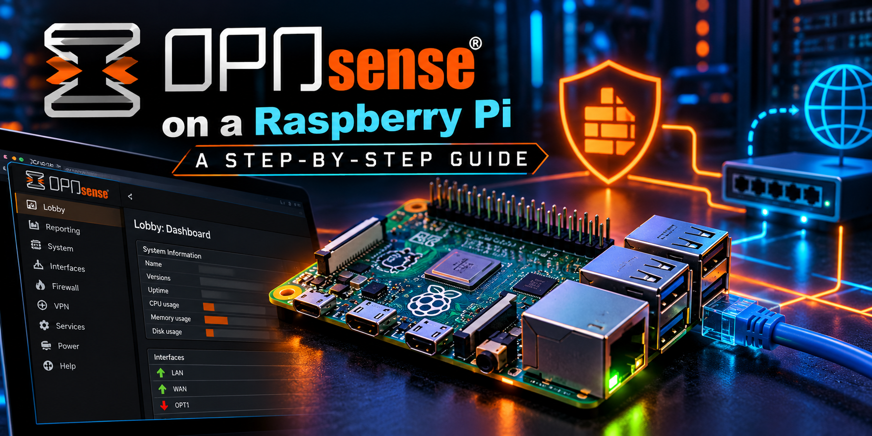
OPNsense on a Raspberry Pi: A Step-by-Step Guide
Executive Summary
Objective: Stand up a working open source firewall on a Raspberry Pi 4, with a routed WAN and LAN, a web GUI, and a functioning update path.
Target audience: Network and security practitioners building a home lab, a travel router, or a small branch test box who already know basic firewall concepts.
Here is the part most guides skip: pfSense does not run on a Raspberry Pi. pfSense CE is built for amd64 (x86-64) only, and the ARM builds of pfSense Plus are locked to Netgate’s own appliances. There is no image to download, and no supported way to build one.
The closest thing you can run on a Pi is OPNsense, the FreeBSD-based fork that shares pfSense’s lineage, the pf packet filter, and most of the same concepts (interfaces, aliases, rules, NAT, gateways). OPNsense has no official Raspberry Pi image either, but a community-maintained aarch64 build exists, complete with its own firmware update repository. This guide deploys that build on a Pi 4 using UEFI firmware.
Note: Read this before you start: the aarch64 images are unofficial community builds. They are not supported by Deciso or the OPNsense core team. Treat this as a lab or learning platform, not a production perimeter. For production, buy x86 hardware.
Prerequisites and Architecture
Assumed knowledge
- Comfortable at a shell on macOS or Linux, including writing disk images with
dd. - Basic firewall and routing concepts: WAN, LAN, NAT, DHCP, default gateway.
- Able to attach a monitor and keyboard to the Pi for the first boot.
How the boot chain works
A Raspberry Pi does not ship with UEFI, and the community OPNsense image expects it. The fix is the open source Pi Firmware Task Force (pftf) RPi4 UEFI firmware, which lives on a small microSD card. The Pi boots the UEFI firmware from the microSD, and the UEFI firmware then boots OPNsense from a USB SSD.
| Stage | Lives on | What it does |
|---|---|---|
| Pi bootloader (EEPROM) | Onboard SPI flash | Loads the firmware files from the microSD |
| pftf RPi4 UEFI | microSD (FAT32) | Provides UEFI and ACPI to the operating system |
| OPNsense (aarch64) | USB 3.0 SSD | FreeBSD-based firewall, GUI, and services |
Component table
| Component | Requirement | Notes |
|---|---|---|
| Raspberry Pi | Pi 4 Model B, 4 GB or 8 GB | Pi 5 is not recommended, see Gotchas |
| Boot media | microSD, any size (1 GB is plenty) | Holds only the UEFI firmware |
| System disk | USB 3.0 SSD, 16 GB or larger | Avoid running the OS from microSD |
| Second NIC | USB 3.0 Gigabit Ethernet adapter | Realtek RTL8153 or ASIX AX88179 chipset |
| Power | Official 5V 3A USB-C supply | Undervoltage causes USB NIC and SSD drops |
| Console | Micro HDMI monitor and USB keyboard | Needed for first boot only |
| Workstation | macOS or Linux with qemu-img |
Used to convert and write the image |
Lab addressing
| Interface | Device name | Role | Addressing |
|---|---|---|---|
| Onboard Ethernet | genet0 |
LAN | 10.0.1.1/24, DHCP server 10.0.1.100 to 10.0.1.199 |
| USB Ethernet | ue0 |
WAN | DHCP from upstream, or static 198.18.10.2/24 |
The onboard port is the more stable of the two, so it carries the LAN where your management session lives. The USB adapter takes the WAN.
Step-by-Step Implementation
Step 1: Update the Pi bootloader
Goal: Make sure the Pi 4 EEPROM is current before changing how it boots.
Action: Boot the Pi once from any Raspberry Pi OS card and run the update. Skip this step if the board was updated recently.
sudo apt update
sudo apt install -y rpi-eeprom
sudo rpi-eeprom-update -a
sudo reboot
Verification: After the reboot, sudo rpi-eeprom-update reports the bootloader as up to date.
Step 2: Build the UEFI microSD
Goal: Create the small FAT32 card that gives the Pi a UEFI environment.
Action: Download the latest RPi4_UEFI_Firmware_v<version>.zip from the pftf/RPi4 releases page on GitHub. Format the microSD as FAT32 with an MBR partition table and extract the zip contents to the root of the card.
macOS (replace diskN with your microSD, confirmed through diskutil list):
diskutil list
diskutil eraseDisk FAT32 UEFI MBRFormat /dev/diskN
unzip ~/Downloads/RPi4_UEFI_Firmware_v<version>.zip -d /Volumes/UEFI
diskutil eject /dev/diskN
Linux (replace sdX with your microSD, confirmed through lsblk):
lsblk
sudo parted -s /dev/sdX mklabel msdos mkpart primary fat32 1MiB 100%
sudo mkfs.vfat -F 32 -n UEFI /dev/sdX1
sudo mount /dev/sdX1 /mnt
sudo unzip ~/Downloads/RPi4_UEFI_Firmware_v<version>.zip -d /mnt
sudo umount /mnt
Verification: The root of the card contains RPI_EFI.fd, config.txt, start4.elf, and fixup4.dat. If those files sit inside a subfolder, the Pi will not find them.
Step 3: Download and convert the OPNsense image
Goal: Get the community aarch64 build and turn it into a raw disk image.
Action: Open the releases page of the maurice-w/opnsense-vm-images repository on GitHub and download the aarch64 image with the EFI console and UFS file system. For the 26.7 series the file follows the pattern OPNsense-26.7-ufs-efi-vm-aarch64.qcow2.bz2. Confirm the exact name on the release page, since it changes with each version.
Pick the efi console variant, not serial. The EFI variant gives you the console on HDMI with a USB keyboard.
The image ships in QCOW2 format for hypervisors, so convert it to raw before writing it to a physical disk.
# macOS
brew install qemu

# Debian or Ubuntu
sudo apt install -y qemu-utils

# Both
cd ~/Downloads
bunzip2 OPNsense-26.7-ufs-efi-vm-aarch64.qcow2.bz2
qemu-img convert -f qcow2 -O raw \
  OPNsense-26.7-ufs-efi-vm-aarch64.qcow2 opnsense.raw
qemu-img info opnsense.raw
Verification: qemu-img info reports file format: raw and a virtual size of roughly 4 GB.
Step 4: Write the image to the USB SSD
Goal: Put OPNsense on the SSD. The root file system grows to fill the disk automatically on first boot.
Note: This erases the target disk. Triple-check the device name before pressing Enter.
macOS:
diskutil list
diskutil unmountDisk /dev/diskN
sudo dd if=opnsense.raw of=/dev/rdiskN bs=4m
sync
diskutil eject /dev/diskN
Linux:
lsblk
sudo dd if=opnsense.raw of=/dev/sdX bs=4M status=progress conv=fsync
sudo eject /dev/sdX
Verification: dd finishes with a record count and no I/O errors. Do not mount or modify the disk afterward. The image must reach its first boot untouched.
Step 5: First boot and UEFI settings
Goal: Boot into the UEFI setup and remove the default 3 GB memory cap.
Action:
- Insert the UEFI microSD. Plug the SSD into a blue USB 3.0 port and the USB Ethernet adapter into the other blue port.
- Connect the monitor and keyboard. Leave the network cables unplugged for now.
- Power on and press Esc when the Raspberry Pi logo appears to enter UEFI setup.
- Go to Device Manager > Raspberry Pi Configuration > Advanced Configuration.
- Set Limit RAM to 3 GB to Disabled. Leave System Table Selection at ACPI.
- Press F10 to save, then Esc back to the main menu.
- Go to Boot Maintenance Manager > Boot Options > Change Boot Order and move the USB SSD to the top. Commit the change.
- Choose Reset to reboot.
Verification: The FreeBSD boot loader menu appears, followed by kernel messages and then the OPNsense console. The first boot takes a few minutes while the root partition expands.
Step 6: Assign interfaces at the console
Goal: Map the onboard NIC to LAN and the USB NIC to WAN.
Action: On first boot OPNsense asks to assign interfaces. If you miss the prompt, log in as root with the default password opnsense and choose option 1) Assign interfaces. Answer the prompts as shown.
Do you want to configure LAGGs now? [y/N]: n
Do you want to configure VLANs now? [y/N]: n

Enter the WAN interface name or 'a' for auto-detection: ue0
Enter the LAN interface name or 'a' for auto-detection: genet0
Enter the Optional interface 1 name or 'a' for auto-detection:
(press Enter to finish)

Do you want to proceed? [y/N]: y
Verification: The console banner lists LAN (genet0) and WAN (ue0). If ue0 is not offered as a choice, the USB adapter was not detected. Jump to Troubleshooting.
Step 7: Set the LAN address and DHCP scope
Goal: Move the LAN off the default 192.168.1.1/24 to the lab range and enable DHCP.
Action: Choose option 2) Set interface IP address, select the LAN interface, and answer the prompts.
Configure IPv4 address LAN interface via DHCP? [y/N]: n
Enter the new LAN IPv4 address: 10.0.1.1
Enter the new LAN IPv4 subnet bit count: 24
For a LAN, press <ENTER> for none: (press Enter)
Configure IPv6 address LAN interface via WAN tracking? [Y/n]: n
Configure IPv6 address LAN interface via DHCP6? [y/N]: n
Enter the new LAN IPv6 address. Press <ENTER> for none: (press Enter)
Do you want to enable the DHCP server on LAN? [y/N]: y
Enter the start address of the IPv4 client address range: 10.0.1.100
Enter the end address of the IPv4 client address range: 10.0.1.199
Do you want to change the web GUI protocol from HTTPS to HTTP? [y/N]: n
Now cable it up: onboard Ethernet to your LAN switch or laptop, USB Ethernet to the upstream modem or router.
Verification: The console prints the GUI URL as https://10.0.1.1. A client plugged into the LAN receives an address in the 10.0.1.100 to 10.0.1.199 range.
Step 8: Run the GUI setup wizard
Goal: Finish base configuration from the web interface.
Action: Browse to https://10.0.1.1, accept the self-signed certificate warning, and log in as root / opnsense. Walk through the wizard:
- General: set hostname (for example
pi-fw), domain, and upstream DNS servers. - WAN: leave at DHCP, or set a static address such as 198.18.10.2/24 with gateway 198.18.10.1.
- WAN options: keep Block private networks enabled only if the WAN is a true public address. If the Pi sits behind another router on RFC 1918 space, clear it.
- LAN: confirm 10.0.1.1/24.
- Root password: change it now. Do not skip this.
- Apply and let the services reload.
GUI verification: Lobby > Dashboard shows the system information widget with the aarch64 architecture, and Interfaces > Overview shows both LAN and WAN as up with addresses.
Step 9: Update from the aarch64 firmware repository
Goal: Confirm the update path works and bring the system current.
Action: Official OPNsense mirrors carry amd64 packages only. The community image is preconfigured for the aarch64 repository at opnsense-update.walker.earth and includes its signing fingerprint. Confirm that from the shell (console option 8) Shell):
cat /usr/local/etc/pkg/repos/OPNsense.conf
opnsense-version
Then go to System > Firmware > Status, click Check for updates, and apply what is offered. The box reboots if the kernel or base system changes.
Note: Do not switch the mirror to an official OPNsense mirror under System > Firmware > Settings. Those mirrors have no aarch64 packages and updates will fail. Community aarch64 releases can trail the official amd64 releases by a short time.
GUI verification: System > Firmware > Status reports that the system is up to date, and opnsense-version shows a 26.7.x release on aarch64.
Step 10: Baseline hardening and housekeeping
Goal: Close the obvious gaps before you put traffic through the box.
- Swap: the image ships without a swap partition. Enable the 2 GB swap file under System > Settings > Miscellaneous.
- Offloading: under Interfaces > Settings, keep hardware checksum, TSO, and LRO offload disabled. USB NICs misbehave with offloads enabled.
- Admin access: under System > Settings > Administration, leave SSH disabled unless you need it, and if you enable it, permit key-based login only.
- Time: confirm NTP is syncing under Services > Network Time > Status. The Pi has no battery-backed clock, and bad time breaks certificate validation.
- Backup: download the config from System > Configuration > Backups once the box is working.
GUI verification: System > Settings > Miscellaneous shows the swap file option checked, and the dashboard reports swap in use after the next reboot.
Optional: single-NIC design with VLANs
If you own a managed switch, you can skip the USB adapter and run WAN and LAN as tagged VLANs on the onboard port. In Step 6, answer y to the VLAN prompt and create two VLANs on genet0, for example tag 10 for LAN and tag 99 for WAN. Assign genet0_vlan99 as WAN and genet0_vlan10 as LAN. On the switch, trunk both VLANs to the Pi, put the modem on an untagged VLAN 99 port, and put clients on untagged VLAN 10 ports. Both directions share one gigabit link, but you remove the USB NIC, which is the least reliable part of the build.
Verification and Validation
Run these from the OPNsense shell (console option 8).
# Version and architecture
opnsense-version
uname -m

# Full RAM visible (should reflect 4 GB or 8 GB, not 3 GB)
sysctl hw.physmem

# Both NICs present, with link and addresses
ifconfig genet0
ifconfig ue0

# Default route and upstream reachability
netstat -rn -f inet | head
ping -c 3 1.1.1.1
drill opnsense.org

# Packet filter is enabled and holding state
pfctl -s info | head -5
pfctl -s nat
| Check | Expected result |
|---|---|
uname -m |
arm64 |
sysctl hw.physmem |
A value near your installed RAM, well above 3221225472 |
ifconfig genet0 |
status: active, inet 10.0.1.1 |
ifconfig ue0 |
status: active, with a WAN address |
ping -c 3 1.1.1.1 |
3 packets received, 0.0% packet loss |
pfctl -s info |
Status: Enabled |
pfctl -s nat |
An outbound NAT rule on ue0 for 10.0.1.0/24 |
Final end-to-end test: from a LAN client, confirm it received a 10.0.1.x lease, can resolve names, and can browse the internet. Then check Firewall > Log Files > Live View and confirm you see the client’s traffic passing on LAN and unsolicited inbound traffic blocked on WAN.
Troubleshooting and Gotchas
1. Rainbow screen, or the Pi never reaches UEFI
The firmware files are missing, nested in a folder, or the card is not FAT32 with an MBR table.
- Re-check that
RPI_EFI.fdandstart4.elfare in the root of the card. - Reformat as FAT32 with MBR (not GPT, not exFAT) and extract again.
- Run Step 1. Very old Pi 4 bootloaders have trouble with newer firmware files.
2. UEFI loads but OPNsense does not boot
- Confirm the SSD appears under Boot Maintenance Manager > Boot Options. If it does not, try a different USB port or enclosure. Some USB-to-SATA bridges are not enumerated reliably at boot.
- Confirm you wrote the converted
opnsense.rawfile, not the.qcow2file. Writing QCOW2 directly produces an unbootable disk. - Confirm you downloaded the
aarch64image and notamd64.
3. The USB NIC is missing or drops under load
Check whether FreeBSD sees the adapter and which driver attached:
usbconfig
dmesg | grep -E "ure0|axge0|ue0|genet0"
ifconfig -l
- No
ue0at all: the chipset is not supported. Stick with Realtek RTL8153 (uredriver) or ASIX AX88179 (axgedriver). - Link flaps or resets under load: this is almost always power. Use the official 3A supply, or move the SSD to a powered USB hub.
- If
genet0is missing, enter UEFI setup and change System Table Selection to ACPI + Devicetree, then reboot.
4. Root file system did not grow
If df -h / still shows about 4 GB after first boot, the automatic growth did not run. Fix it by hand:
gpart recover da0
gpart show da0
gpart resize -i 3 da0
growfs -y /
df -h /
Use the partition index that gpart show lists for the freebsd-ufs partition. It is not always 3.
5. Updates fail or show no packages
- Check that
/usr/local/etc/pkg/repos/OPNsense.confstill points atopnsense-update.walker.earth. - Check that the mirror was not changed in System > Firmware > Settings.
- Check system time with
date. A wrong clock breaks TLS to the repository.
Gotchas worth knowing before you commit
- Raspberry Pi 5: not a good target today. FreeBSD support for the Pi 5 is incomplete, and community reports describe the onboard Ethernet as non-functional. Use a Pi 4.
- VPN throughput: the Pi 4 CPU has no AES hardware acceleration, so IPsec, OpenVPN, and WireGuard throughput is CPU-bound and well below line rate.
- Plugins: most plugins are built for aarch64, but anything that depends on x86-only binaries will not be available.
- Wi-Fi: the onboard Wi-Fi is not usable as an access point here. Use a dedicated AP on the LAN.
- Support: forum help for aarch64 comes from the community thread, not from the vendor.
Bottom Line
You cannot put pfSense on a Raspberry Pi, and no amount of searching will produce an image. What you can do is run OPNsense, its closest relative, on a Pi 4 with UEFI firmware, a USB SSD, and a second NIC. For a lab, a travel firewall, or a place to learn pf-based policy without buying an appliance, it does the job. For anything you would be paged about, spend the money on x86.
References
- maurice-w/opnsense-vm-images (unofficial aarch64 and amd64 images): https://github.com/maurice-w/opnsense-vm-images
- OPNsense aarch64 firmware repository thread: https://forum.opnsense.org/index.php?msg=230729
- pftf Raspberry Pi 4 UEFI firmware: https://github.com/pftf/RPi4
- FreeBSD forums, Raspberry Pi 5 status: https://forums.freebsd.org/threads/raspberry-pi-5-status.91406/
Recent posts
-

-

DNS is one of those technologies that quietly underpins... Full Story
-

BGP issues on FortiGate firewalls usually trace back to... Full Story
-

Every time your laptop talks to your router, a... Full Story
-

If you've spent any time configuring NAT on a... Full Story
-

If you have spent any time configuring firewall policies... Full Story
-

High availability on FortiGate is one of those features... Full Story
-

If you've configured SD-WAN on a FortiGate, you've almost... Full Story
-

FortiLink is the management protocol that turns a FortiSwitch... Full Story
-

FortiSwitches are pretty rock solid from Mean Time Between... Full Story
-

This is a quicky tip. Have you ever gone... Full Story
-

DNS is one of those quiet pieces of internet... Full Story
-

This article is an updated version of the previous... Full Story
-

You will add ns2 as a secondary (slave) BIND9... Full Story
-

In the process of deploying my lab, I needed... Full Story
-

RFC 8805, used to be known as Self-Correcting IP... Full Story
-

Years back, I wrote an article about certificate pinning. ... Full Story
-

FortiGates have the ability to send alerts to Microsoft... Full Story
-

In this post, I am going to walk through... Full Story
-

Troubleshooting VoIP on a FortiGate can feel like trying... Full Story
-

Prior to FortiOS 7.0, there were three commands to... Full Story
-

In this post, I am going to go over... Full Story
-

What we are going to do: We are going... Full Story
-

Choosing between FGCP (FortiGate Clustering Protocol) and FGSP (FortiGate... Full Story
-

Creating a VLAN on macOS (The "Pro" Move) A... Full Story
-

This blog post explores the logic behind how macOS... Full Story
-

Pretty Fly for a Wi-Fi Tell My Wi-Fi Love... Full Story
-

Part of my daily gig is creating BoMs (Bill-of-Materials)... Full Story
-

ICMP introduces several security risks, but careful filtering, rate... Full Story
-

The command diag debug application dhcps -1 enables full... Full Story
-

In the world of FortiOS, execute tac report is... Full Story
-

LLDP; What is it The Link Layer Discovery Protocol... Full Story
-

What it actually does When you run diagnose fdsm... Full Story
-

Monkey Bites are bite-sized, high-impact security insights designed for... Full Story
-

I have run macOS in macOS with Parallels but... Full Story
-

Don't be confused with my other FortiNAC posts where... Full Story
-

This is the third session in a multi-part article... Full Story
-

Today I was configuring key-based authentication on a FortiGate... Full Story
-

Netcat, often called the "Swiss Army knife" of networking,... Full Story
-

At its core, IEEE 802.1X is a network layer... Full Story
-

In case you did not see the previous FortiNAC... Full Story
-

This is our 5th session where we are going... Full Story
-

Now that we have Wireshark installed and somewhat configured,... Full Story
-

The Philosophy of Packet Analysis Troubleshooting isn't about looking... Full Story
-

1. Executive Summary Objective: Get a working, persistent nftables... Full Story
-

Executive Summary Objective: Identify every cleartext and unauthenticated legacy... Full Story
-

Executive Summary Objective: Roll an expiring SAML signing certificate... Full Story